NEC R 37 Xtra User Manual
Page 17
17
23
24
Pin No.
1
2
3
12
13
14
15
4
5
6
7
8
11
10
9
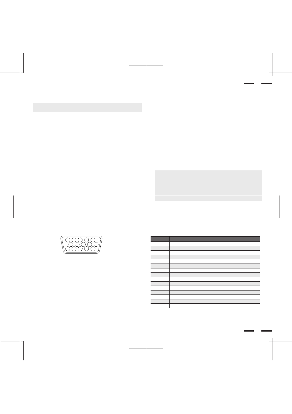
D-Sub 15 Pin RGB Signal Composition
Pin Assignments and Signal Levels for 15 pin RGB (Analog)
Signal to be connected (D-SUB 15 pin)
RED
GREEN or Sync Green
BLUE
SDA
H. or Composite sync
V.SYNC
SCL
GND
GND
GND
GND
GND
GND
No Connection
No Connection
D-SUB 15pin RGB Input Connector (ANALOG ONLY)
1
2
3
4
5
11
12
13
14
15
6
7
8
9
10
Daisy-chaining Your monitors
The REMOTE IN/OUT terminals allow you to control monitors by one remote
control.
NOTE: The connection of three XP37 Xtra/XM37 Xtra monitors or more with
THROUGH OUT (VIDEO 1 or 2) terminals may degrade image quality.
To do so:
When using the VIDEO inputs:
THROUGH OUT (VIDEO 1) Connections
1. Connect THROUGH OUT 1 BNC or S-VIDEO 1 OUT to external compo-
nents to relay the signal input at VIDEO 1 IN(BNC-type), or S-VIDEO 1 IN.
2. Connect the external component mono audio or stereo left channel audio
input to L AUDIO.
3. Connect the external component stereo right channel audio input to R AU-
DIO.
4. Set the 75
Ω
/HIGH impedance select switch of the corresponding input sig-
nal (BNC, S-VIDEO) on all but the last monitor to “HIGH” position. Only the
last monitor is set to “75
Ω
” position.
THROUGH OUT (VIDEO 2) Connections
1. Connect THROUGH OUT 2 BNC or S-VIDEO 2 OUT to external component
to relay the signal input at VIDEO 2 IN(BNC-type) or S-VIDEO 2 IN.
2. Connect the external component mono audio or stereo left channel audio
input to L AUDIO.
3. Connect the external component stereo right channel audio input to R AU-
DIO.
4. Set the 75
Ω
/HIGH impedance select switch of the corresponding input signal
(BNC, S-VIDEO) on all but the last monitor to “HIGH” position. Only the last
monitor is set to the “75
Ω
” position.
5. Connect the REMOTE OUT of the monitor to the REMOTE IN of the next
monitor using the optional remote cable.
When using the RGB inputs:
THROUGH OUT Connections
1. (RGB1): Connect Mini D-Sub 15-pin THROUGH OUT to an RGB input con-
nector of other monitors.
(RGB2): Connect the R.G.B.H/CS and V THROUGH OUT terminals to relay
the signal input at the R.G.B.H/CS and V IN terminals.
2. Set all the 75
Ω
/HIGH impedance select switches on all but the last monitor to
“HIGH” position. Only the last monitor is set to the “75
Ω
” position.
3. Connect the REMOTE IN of the monitor to the REMOTE OUT of the next
monitor using the optional remote cable.
NOTE: ''Plug and Play'' is available only for the monitor connected directly to
a personal computer with the Mini D-Sub 15-pin RGB connector. Therefore,
''Plug and Play'' does not work for monitors connected with the THROUGH
OUT terminal. This is because only the RGB video, the horizontal, and the
vertical sync. signal is output from the THROUGH OUT terminals.
NOTE: ''Plug and Play'' is not available for the RGB 2 BNC terminals.