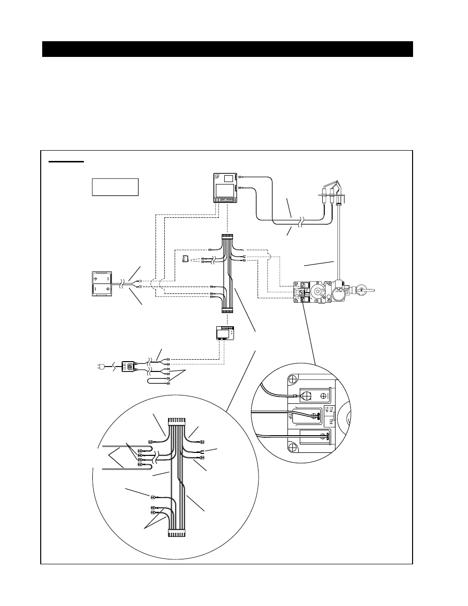
Wiring diagram, See detail for optional wall switch gd-660 wiring – Napoleon Fireplaces Castlemore GDS26N User Manual
Page 24
24
W415-0607 / A / 01.18.08
FIGURE 46
B
ATTERY
H
OLDER
G
AS
V
ALVE
P
ILOT
A
SSEMBLY
I
GNITION
M
ODULE
P
ILOT
G
AS
L
INE
Orange
(I)
[through
independent
conduit]
Yellow
(S)
[through
Gas line
conduit]
AC A
DAPTOR
B
ATTERY
R
ELAY
Red (3 Volt)
Red
Black
W
IRE
H
ARNESS
N
OTE
: W
IRE TAGS
ARE BRACKETED
Brown
(SWI)
Black
(-)
Red
(+)
Green x2
(TH)
Orange x2
(THTP)
Black
Yellow
Blue
Black
(TP)
M
ODULE
P
LUG
R
ELAY
P
LUG
Black
Green
Orange
Black (12 Volt)
*
To Accent Light &
Night Light
TM
Switch
To Optional
Wall Switch
(GD-660)
M
AIN
B
URNER
S
WITCH
*
* See detail for optional
wall switch GD-660 wiring.
Main Burner Switch
WIRING DIAGRAM
The main burner on/off switch and Night Light
TM
switch is
located behind lower access panel. For ease of accessibility,
optional remote wall switches may be installed in a convenient
location for both burner and light operation.
The recommended maximum lead length depends on wire
size:
WIRE SIZE
MAX. LENGTH
14
gauge 100
feet
16
gauge
60
feet
18
gauge
40
feet
Route 2-strand (solid core) wire through the electrical hole
located at the bottom left side of the unit. Connect the
wires from the wall switch to the two corresponding spade
connectors on the back of the on/off switches located behind
the lower access panel.