Thetford Norcold 453 User Manual
Page 10
supply connects to the terminal block at the rear of
the refrigerator (See Figure 9 on page 8). The 12 volt
DC should enter the refrigerator’s enclosure near the
refrigerator’s terminal block. The 12 volt DC connects
at (2) one quarter inch quick connects. The positive
DC input lead connects to terminal marked (+), and
the DC ground input lead connects to terminal
marked (-).
CAUTION: Correct polarity must be ob-
served when connecting the DC supply.
Do not use the chassis of the refrigerator
or the vehicle frame as one of the conduc-
tors. Connect DC supply wires at the bat-
tery and route to the refrigerator.
The distance the current travels from the battery to
the refrigerator dictates the wire size. Undersized
wire can result in a voltage drop, which will affect the
wattage output of the DC heater and result in re-
duced refrigerator performance. Norcold recommends
the installation of a fuse in the supply wiring between
the battery and the refrigerator. For optimum protec-
tion, install the fuse as close to the battery as possi-
ble.
WARNING: A circuit overload can result in
an electrical fire when undersized wires or
improperly sized fuses are used. To pre-
vent a possible electrical fire, follow
R.V.I.A. A119.2 Standards, Norcold’s wire
size and fuse specifications, or applicable
state and local codes.
TABLE 3
12 VOLT SUPPLY WIRING AND FUSE SIZE
482, 462
452, 442
483, 463
453, 443
min.
wire
size
max.
fuse
size
min.
wire
size
max.
fuse
size
Min.
wire
size
max.
fuse
size
0 - 20’
18
AWG
6 Amp
10
AWG
30
Amp
12
AWG
20
Amp
over
20’
18
AWG
6 Amp
8
AWG
40
Amp
10
AWG
30
Amp
If a wire size is installed which is larger than the
minimum size indicated the table above, it must be
fused in accordance with the R.V.I.A. A119.2 stand-
ard or local governing codes.
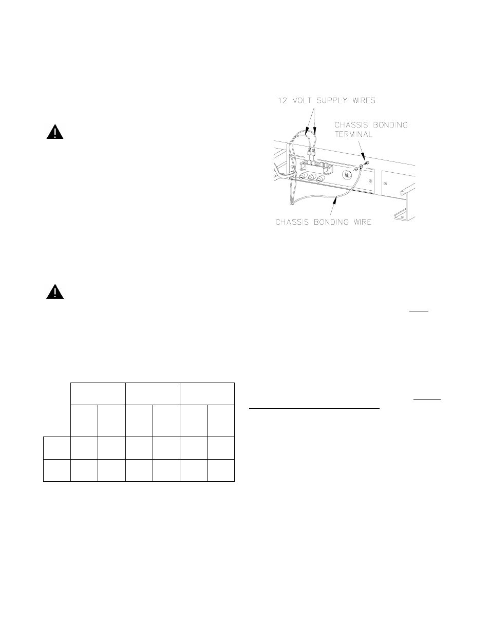
Chassis Bonding Connection
A No. 8 AWG copper conductor is commonly used
to meet the chassis bonding requirements of the Na-
tional Electric Code (ANSI/NFPA No. 70, Art. 551).
When this conductor is used to bond the non-current
carrying metal parts of the refrigerator, a No. 10-32
bonding terminal is provided to make the connection.
(See Figure 10 ).
Hypot Test
A Dielectric Strength test (hypot) has been con-
ducted at the factory; this refrigerator does not re-
quire an additional test. If hypot tests are conducted
on the vehicle’s 12 volt circuit, the 12 volts must be
disconnected from the refrigerator to protect the
flame ignition circuit.
Testing the Vehicle’s Gas Supply Piping
When installation of the refrigerator is complete, the
propane gas supply piping must be inspected and
tested for leaks from the refrigerator to the main gas
supply tank. Use a leak detection solution. Do not
test for leaks with an open flame.
If compressed air is used for leak testing, the gauge
pressure must not exceed 1/2 pound per square inch
(14 inches water column).
The appliance and its individual shut-off valve (Fig-
ure 11 on page 10) must be disconnected from the
gas supply system during any pressure testing of that
system at test pressures greater than 1/2 psig (14
inches water column).
The appliance must be isolated from the gas supply
system by closing its individual manual shut-off valve
(Figure 11 on page 10) during any pressure testing
of that system at test pressure equal to or less than
1/2 psig (14 inches water column).
Check the gas pressure to the refrigerator without
other gas appliances operating. The pressure should
not exceed 11 inches water column. With other appli-
ances operating the pressure should not be less than
10.5 inches water column.
Figure 10
10