Table 4. ni 654x ddc connector pins, Ble 4 – National Instruments PXI-6561/6562 User Manual
Page 20
NI Digital Waveform Generator/Analyzer Guide
20
ni.com
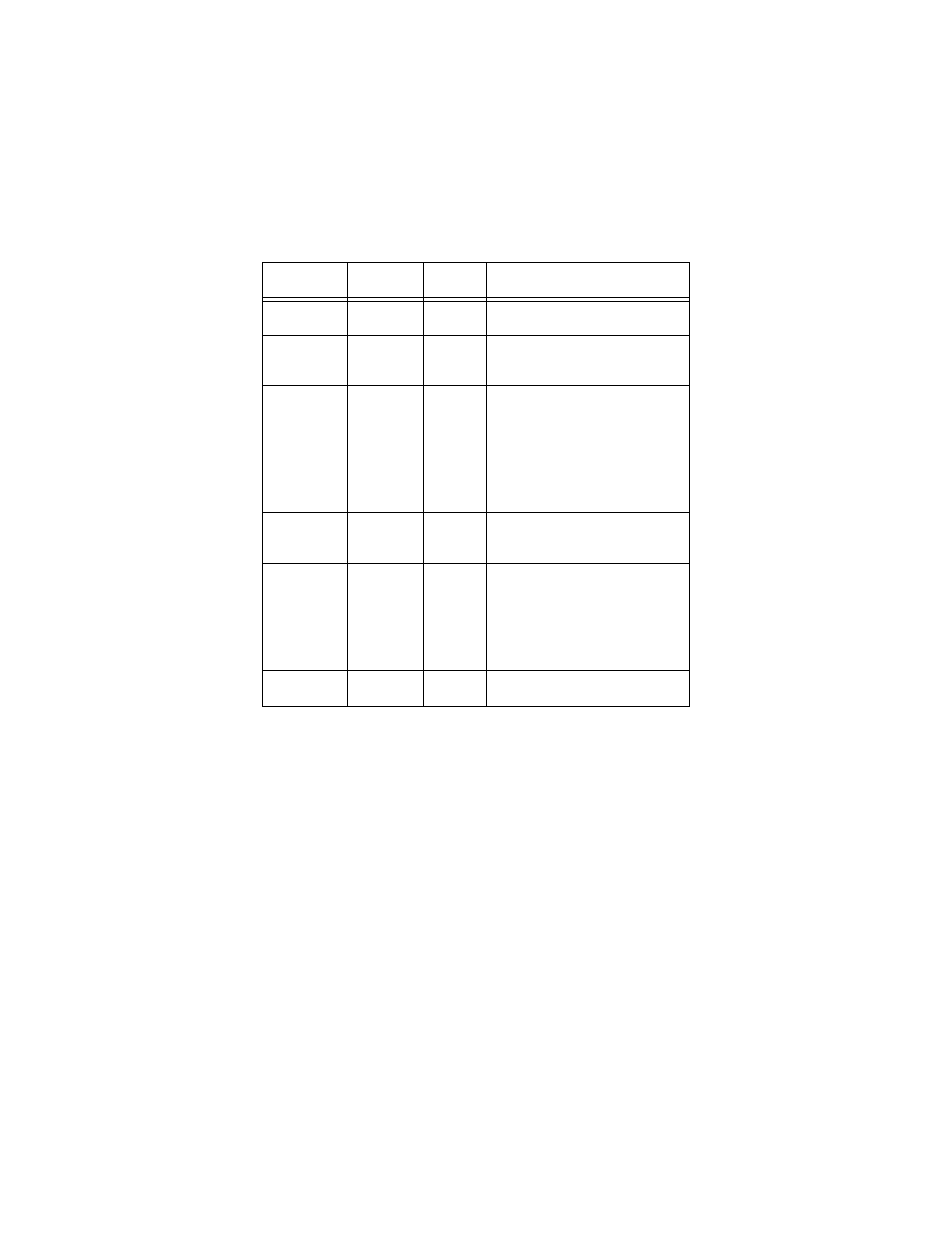
Table 4. NI 654X DDC Connector Pins
Pins
Signal
Name
Signal
Type
Signal Description
33
DDC CLK
OUT
Control
Output terminal for the exported
Sample clock.
67
STROBE
Control
Terminal for the external Sample clock
source which can be used for pattern
acquisition.
1, 3, 5, 7, 9,
11, 13, 15, 17,
19, 21, 23, 25,
27, 29, 31, 35,
37, 39, 41, 43,
45, 47, 49, 51,
53, 55, 57, 59,
61, 63, 65
DIO <0..31>
Data
Bidirectional digital I/O data channels
0 through 31.
26, 30, 64
PFI <1..3>
Control
Input terminals to the NI 654X for
external triggers, or output terminals
from the NI 654X for events.
2, 4, 6, 10, 12,
14, 16, 18, 20,
22, 24, 28, 32,
34, 36, 38, 40,
42, 44, 46, 48,
50, 54, 56, 58,
62, 66
GND
Ground
Ground reference for signals.
8, 52, 60
RESERVED
N/A
These terminals are reserved for future
use. Do not connect to these pins.