Warning, Startup and checkout – Nordyne R-410A User Manual
Page 7
7
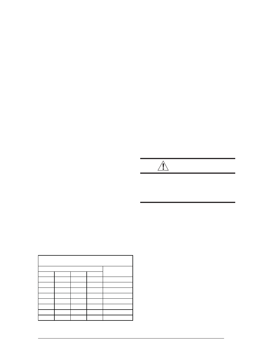
Wire Size based on N.E.C. for 60° type copper con-
ductors.
COPPER WIRE SIZE — AWG
(1% Voltage Drop)
Supply Wire Length-Feet
Supply Circuit
200
150
100
50
Ampacity
6
8
10
14
15
4
6
8
12
20
4
6
8
10
25
4
4
6
10
30
3
4
6
8
35
3
4
6
8
40
2
3
4
6
45
2
3
4
6
50
Wiring Diagram/Schematic — A wiring
diagram/schematic is located on the inside cover
of the electrical box of the outdoor unit. The
installer should become familiar with the wiring
diagram/schematic before making any electrical
connections to the outdoor unit.
Outdoor Unit Connections — The outdoor
unit requires both power and control circuit
electrical connections. Refer to the unit wiring
diagram/schematic for identifi cation and location
of outdoor unit fi eld wiring interfaces.
Control Circuit Wiring — The outdoor unit is
designed to operate from a 24 VAC Class II control
circuit. Control circuit wiring must comply with
the current provisions of the “National Electrical
Code” (ANSI/NFPA 70) and with applicable local
codes having jurisdiction.
Thermostat connections should be made in
accordance with the instructions supplied with
the thermostat, and with the instructions supplied
with the indoor equipment. A typical residential
installation with a heat pump thermostat and air
handler are shown below.
Electrical Power Wiring — Electrical power
wiring must comply with the current provisions
of the “National Electrical Code” (ANSI/NFPA
70) and with applicable local codes having
jurisdiction. Use of rain tight conduit is
recommended. Electrical conductors shall have
minimum circuit ampacity in compliance with the
outdoor unit rating label. The facility shall employ
electrical circuit protection at a current rating no
greater than that indicated on the outdoor unit
rating label. Refer to the unit wiring diagram for
connection details.
Minimum Circuit Ampacity — Electrical wiring
to the equipment must be compatible and in
compliance with the minimum circuit ampacity
listed on the outdoor unit data label.
Maximum Fuse/Circuit Breaker Size — Circuit
protection for the outdoor unit must be compatible
with the maximum fuse/circuit breaker size listed
on the outdoor unit data label.
Disconnect Switch — An electrically compatible
disconnect switch must be within line of sight of
the outdoor unit. This switch shall be capable of
electrically de-energizing the outdoor unit.
Optional Equipment — Optional equipment
requiring connection to the power or control
circuits must be wired in strict accordance with
current provisions of the “National Electrical
Code” (ANSI/NFPA 70), with applicable local
codes having jurisdiction, and the installation
instructions provided with the equipment.
Optional Equipment (e.g.: liquid line solenoid
valves, hard start kits, low suction pressure
cutout switch kit, high pressure cutout switch kit,
refrigerant compressor crankcase heater, etc.)
should be installed in strict accordance with the
manufacturer’s installation instructions.
STARTUP AND CHECKOUT
WARNING:
Ensure electrical power to the unit is
off prior to performing the following
steps. Failure to do so may cause
personal injury or death.
Air Filters — Ensure air fi lters are clean and in
place prior to operating the equipment.
Thermostat — Set the room thermostat function
switch to OFF, fan switch to AUTO, and adjust the
temperature setpoint to its highest setting.
Prior to applying electrical power to the outdoor
unit, ensure that the unit has been properly and
securely grounded, and that power supply
connections have been made at both the facility
power interface and outdoor unit.
Outdoor Unit — Ensure the outdoor coil and
top of the unit are free from obstructions and
debris, and all equipment access/control panels
are in place.
Using extreme caution, apply power to the unit
and inspect the wiring for evidence of open,
shorted, and/or improperly wired circuits.