Niles Audio PERFORMANCE PR6 User Manual
Page 9
Installation of
Brackets, Frames
and Grilles in
Existing Walls
IMPORTANT: Before you cut into any
wall, review the sections on running
wire and speaker placement.
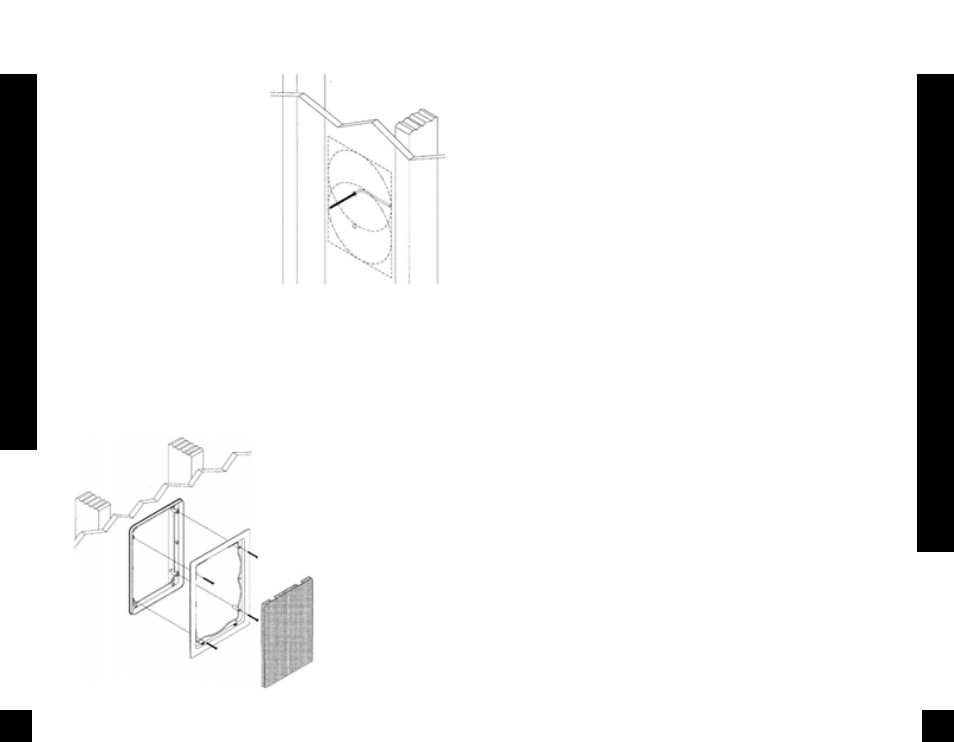
1. Drill a 1/8” pilot hole just barely
through the wallboard or dry wall (1/2”
to 5/8” deep in most homes) about an
inch below the center of your proposed
speaker location (an inch to the side if
you are mounting the speaker horizon-
tally). BE VERY CAREFUL NOT TO DRILL
THROUGH EXISTING WIRES, PIPES, OR
STRUCTURE. IF YOU FEEL ANY EXTRA
RESISTANCE AS YOU ARE DRILLING,
STOP. Cut a piece of coat hanger equal
to the width of the bracket. Bend the wire
in half creating a right angle. Poke the “L-
shaped” wire into the pilot hole and turn
it in a complete circle. If it turns freely,
repeat the procedure from a hole about
an inch above the center of your proposed
speaker location (See Figure 11).
If the wire’s movement is obstructed by a
pipe or cable, fill the hole (s) with spack-
le or other patching compound and try
another location.
2. When determining the final location of
the cutout keep in mind that the frame and
bracket will extend beyond the cutout.
Make sure that you do not place the edge
of the cutout directly next to a stud. Locate
the studs using a stud sensor or hand-
knocking. Once you have determined the
correct position for the cutout, hold the
supplied template up to the wall surface.
Level the template in either the horizontal
or the vertical position and mark the wall
with a
pencil. Drill the four corners
with a 1/4” drill bit.
3. If you are cutting a painted
or wall papered drywall use
a sheetrock or keyhole saw.
Cut the hole with the saw at
a 45 degree angle.
15
Installation
of
Brackets, Frames and Grilles in Existing Walls
That way, the drywall section can be
replaced cleanly if there is an unseen
obstruction behind the wall. BE VERY
CAREFUL NOT TO SAW THROUGH
EXISTING WIRES, PIPES, OR STRUCTURE.
IF YOU FEEL ANY EXTRA RESISTANCE AS
YOU ARE CUTTING, STOP.
4. If you are cutting into lath and plaster
walls, use masking tape to outline your
penciled marks, drill the four corners with
a 1/4” bit and use a razor to score the
plaster down to the lath beneath. Then use
a chisel to remove all of the plaster within
the taped outline. Finally, insert a metal
cutting blade into a sabre saw and very
slowly and carefully saw the lath. Sawing
the lath can easily vibrate plaster off the
wall. If you have the patience, use a pair
of tin snips to slowly nip away at the lath
instead. There is no risk with this method,
it is just time consuming.
5. Fill the wall cavity with insulation at this
point. Remember to use equal amounts of
insulation for each speaker.
6. Slip the mounting bracket through the
hole and pull it toward you so that its front
edge slides into the hole and stops in place.
7. Attach the frame to the bracket by
screwing the frame to the bracket using
the supplied screws. Do not overtighten
the screws, this will distort the frame and
the grilles will not fit (this is not perma-
nent, just loosen the screws and the grille
will pop in). The screws should pull the
frame and bracket together (sandwiching
the drywall) so that the frame is abso-
lutely flush with the wall surface. There
should be no gaps between the wall and
the frame (See Figure 12).
Installation of the
Speaker, Sensor
and Grille in New or
Existing Construction
Installing a Niles MS110 MicroSensor
There is a 1/2” round molded “IR Sensor
Knockout” on the face of the speaker baf-
fle. To prevent damage to the crossover
network you must remove the knock-
out from the rear of the speaker. Do not
attempt to remove the knockout with the
speaker face up. Lay the speaker face
down on a clean carpet or rug. Put the
tip of a screwdriver into the center of the
round “knockout” and sharply tap the
screwdriver handle as necessary. Install
the MS110 using its mounting hex nut
and washer so that it is tightly secured to
the speaker. Connect all wires and con-
tinue your installation.
16
Installation
of
the Speaker, Sensor and Grille in New or Existing Construction
Figure 12
Figure 11