Nady Systems IRW-2PA User Manual
Page 7
10
7
3. Connections:
a. Connect the IRW-1S IR Sensors to the IRW-2PA receiver by plugging the sensor
coaxial extension cable plugs into the Infrared Sensor Inputs (1). Each sensor
input will receive both channels A and B signals. To increase mobility and maximum
range, additional sensors can be added by plugging into the two remaining inputs,
or by daisy-chaining sensors. To daisy-chain sensors, disconnect the sensor from the
coaxial extension cable and use the optional IRW-SY Multiple Sensor Y-adapter to
reconnect the original sensor as well as the additional sensor/extension cable.
b. Connect the speakers to the Speaker Output (2) spring clip connector using
speaker cable (not included). The power amp can handle loads of 4Ω impedance or
greater. When using multiple speakers, care must be taken to ensure that the total
impedance is not less than 4Ω and that all speakers are in phase with each other.
Following are some speaker combinations that the amplifier can handle.
One Speaker
4Ω = one 4Ω speaker
8Ω = one 8Ω speaker
16Ω = one 16Ω speaker
Two Speakers
8Ω = 4Ω + 4Ω (wired in series)
4Ω = 8Ω || 8Ω (wired in parallel)
8Ω = 16Ω || 16Ω (wired in parallel)
Four Speakers
4Ω = (4Ω + 4Ω) || (4Ω + 4Ω) (wired in series/parallel)
8Ω = (8Ω || 8Ω) + (8Ω || 8Ω) (wired in series/parallel)
4Ω = 16Ω || 16Ω || 16Ω || 16Ω (wired in parallel)
Six Speakers
6Ω = (4Ω + 4Ω + 4Ω) || (4Ω + 4Ω + 4Ω)
5.3Ω = (8Ω || 8Ω || 8Ω) + (8Ω || 8Ω || 8Ω)
10.6Ω = (16Ω + 16Ω) || (16Ω + 16Ω) || (16Ω + 16Ω)
Eight Speakers
8Ω = (4Ω || 4Ω) + (4Ω || 4Ω) + (4Ω || 4Ω) + (4Ω || 4Ω)
4Ω = (8Ω || 8Ω || 8Ω || 8Ω) + (8Ω || 8Ω || 8Ω || 8Ω)
8Ω = (16Ω || 16Ω || 16Ω || 16Ω) + (16Ω || 16Ω || 16Ω ||16Ω)
c. Connect the AC/AC power supply to the side panel 3-prong AC Power Input (3)
and connect the other end to an AC outlet.
d. If desired, connect an auxiliary device to the IRW-2PA using the Aux Input (4)
1⁄4” jack. This input is designed to accept line level inputs from CD players, MP-3
players, and tape decks. Use a stereo-to-mono adapter cable so that the right signal
is not lost from the stereo mix. If the audio level is too low, try using the Mic Input.
e. If desired, connect a microphone to the Mic Input (5) 1⁄4” jack. This input is
designed to accept mic level to low line level signals.
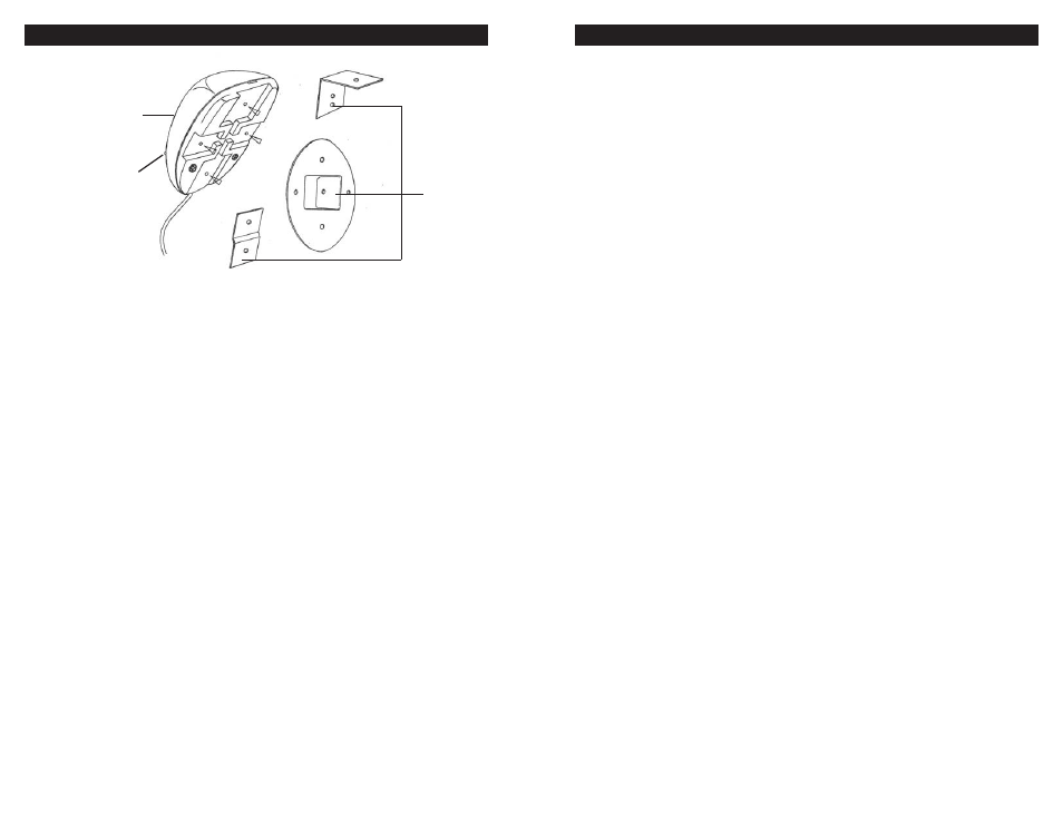
INSTALLATION
(1) IR Receptor
(2) Power LED
(3) Wall Mounts
(2)
(1)
(3)
1. Operation
The IR Sensors act as “antenna” for your infrared wireless microphone system. A
multiple array of wide angle IR-sensitive LED’s in each sensor receives the infra-
red signal emitted by your IR transmitter. The Sensor Power LED (2) will light to
indicate the sensor is properly connected to the IRW-2PA when powered on. The
Channel A and B IR LED indicators, located on the front panel of the IRW-2PA,
will light green when an infrared signal on the corresponding channel is detected.
These sensors should be positioned for maximum range and mobility of the wireless
microphone user.
2. Additional Sensors
To increase mobility and maximum range, additional sensors can be either plugged
into the remaining Infrared Sensor Inputs (1) or daisy-chained with existing sen-
sors using the optional IRW-SY Multiple Sensor Y-adapter.
3. Wall Mounting
The IRW-1S sensors can be mounted on walls using any of the Wall Mounts (3)
included. See the Installation section on pg 6 of this manual for information re sen-
sor positioning.
IRW-1S INFRARED (IR) SENSORS