Newcon Optik LRB 20000 User Manual
Page 22
- Rotate the azimuth dial to align the base reference value with
the zero wheel. Now the rangefinder is aligned with the base
line within 30.00 mils;
- Turn the clamping handle to lock the azimuth dial in the
determined position.
7.5.2. To orient the rangefinder by using the reference directional
angle, proceed as follows:
- Aim the range finder to the reference point, which
directional angle is known;
- Rotate the azimuth dial to set the reference directional angle;
- Turn the clamping handle to lock the azimuth dial in the
determined position.
With the rangefinder oriented, the measurements are taken from
the location point relative to the directional angle of the object
(reference object).
7.5.3. For the magnetic orientation of the rangefinder, proceed as
follows:
- Unscrew the plunger knob all the way out to release the
magnetic needle of the compass;
- Turn the AI around the vertical axis to obtain precise
alignment of the index mark of the circle with the magnetic
needle;
Rotate the azimuth dial to set the magnetic azimuth index
correction.
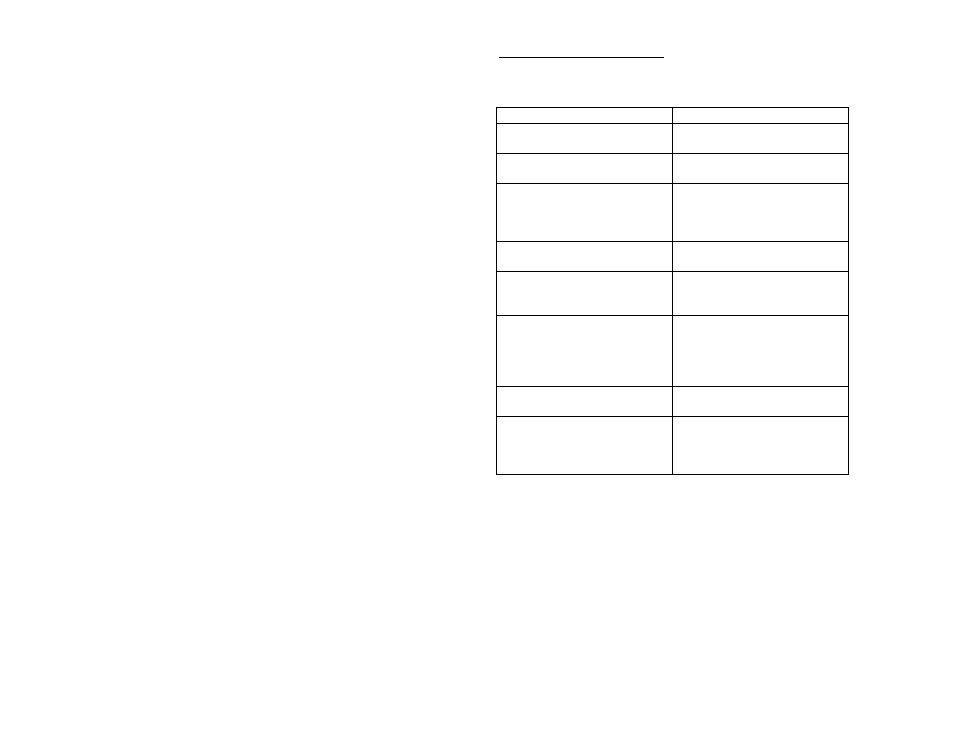
9. SERVICEABILITY TEST
The principal tests to be performed on the range finder are listed
below.
Table 9.1
Items to check, test procedure
Technical requirement
Rangefinder completeness
Range finder is complete with all
components listed in Section 5
Rangefinder exterior
Exterior surfaces are clean and free
from cracks, dents and rust
Exterior of range finder optical
parts (to be checked visually).
Make sure that the unit is off!
Optical surfaces are free from
cracks, scratches, chips, dirt,
grease stains (exterior) and
condensed moisture (interior)
Dehydrator case of range finder
(to be checked visually)
Silica gel is bluish in colour
Battery voltage. Proceed as
directed under 7.3.1
The red Low Battery indicator is
not lit in the left eyepiece of the
rangefinder
Illumination of range finder
Binocular reticle. Check that the
front cover of the rangefinder is
closed and set ILLUM. selector
switch to ON
Binocular reticle is illuminated
Functioning of range finder.
Proceed as directed under 7.3.2.
Measured results are within 5 m of
predetermined range
Setting of zero elevation reference
(ER “0”). Proceed as directed
under 7.6.1.
ER “O” error determined for
vertical angle scale should be
calculated for the elevation
measurements.