Blower installation – Napoleon Fireplaces GDS25P User Manual
Page 7
7
W415-0547 / C / 07.25.06
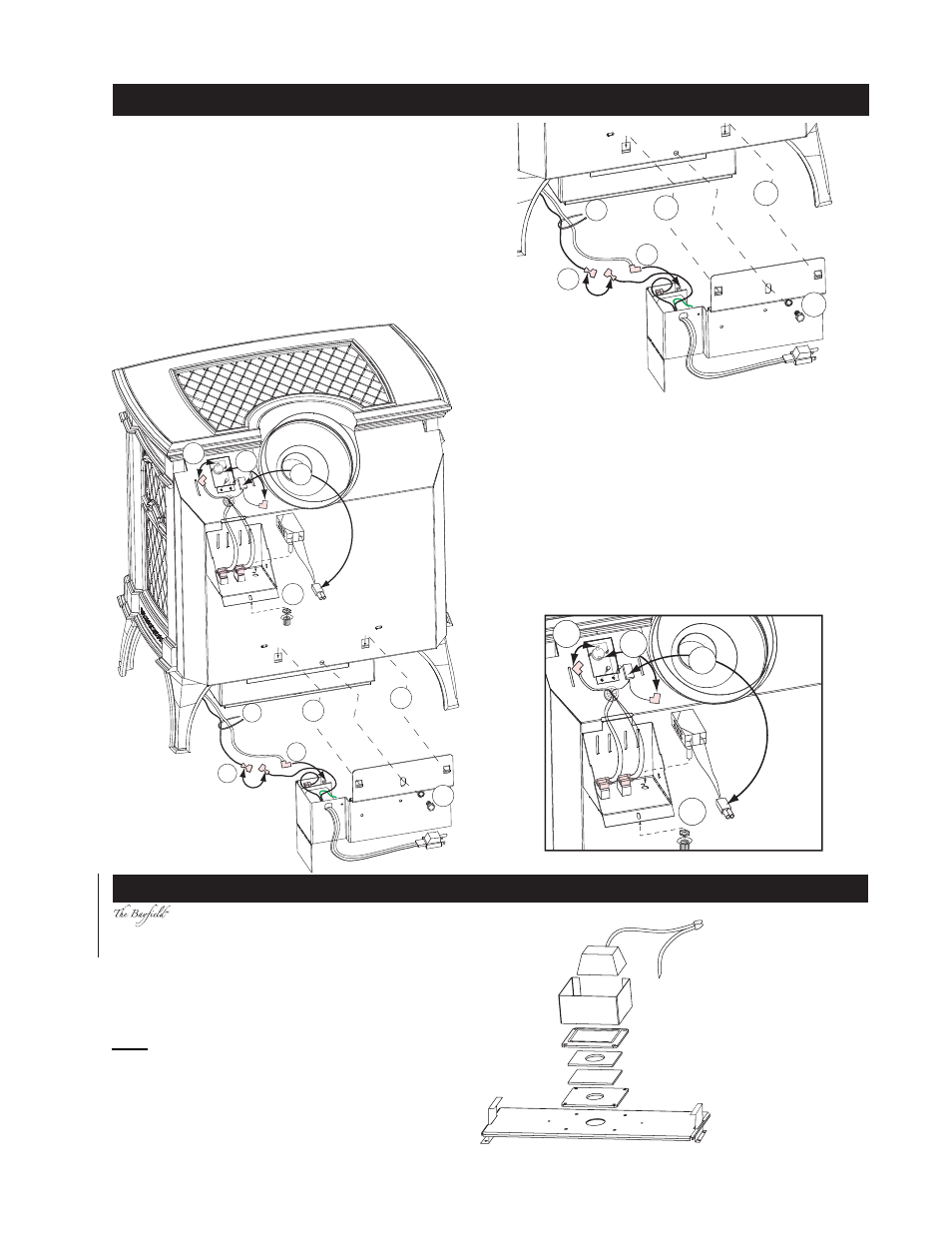
BLOWER INSTALLATION
4
5
8
2
3
1
9
7
7
4
Blower (
SEE
LOCATION
AND
CLEARANCES
)
1. Cut and remove the tie securing the blower switch wires
to the heat shield.
2. Connect the white wire coming from below the unit to the
terminal on the blower.
3. Connect the black blower wire to the black wire coming
from below the unit.
4. Insert the clips on the blower housing into the cutouts in the
rear shield. Push down to lock the clips into position.
5. Secure the blower using the screw and lock washer sup-
plied.
Note: Ensure that all the wires are tucked into the blower
switch housing.
Switches
6. Open the switch housing by removing the top screw.
7. Install the thermodisc bracket as shown, using 2 of the
screws supplied. Connect the fl agged leads to the terminals
of the thermodisc.
Remove the knock out from the housing label.
8. Install the variable speed switch (rheostat) into the housing
with the wires facing up. Secure the switch to the housing
using the pal nut and the knob supplied.
9. Connect the male connector on the switch to the female
connector coming from the unit.
10. Tuck all of the wires into the housing and close. Secure
using the screw removed in step 6.
4
5
2
3
1
4
8
9
7
7
comes equipped with our “Night Light”.
If in the event the lamp or lens needs to be replaced,
follow these instructions.
Disconnect the two wire leads at the wire nut. Remove
the four screws securing the accent lite assembly from
the relief door. Disassemble the lite and the lamp now
can be accessed
Note: Do not handle the lamp (bulb) with bare
fi ngers, protect with a clean dry cloth.
The lamp will pull straight out of the socket. Replace with
Wolf Steel parts only, as lamp and lens are special “high
temperature” products.
When re-installing, ensure integrity of gasket seal.
THE FIREBOX
MUST BE SEALED.
When re-assembling
the light assembly,
care must be taken
with all gaskets.
“Light Leakage”
from above the
cast doors may be
noticed. The holes
in the lamp housing
are necessary for
ventilation and must
not be covered.
NIGHT LIGHT REPLACEMENT
GASKET
RELIEF
DOOR
GLASS LENS
GASKET
COVER PLATE
SHEILD
RAIL
RAIL
WIRE NUT