Led indicators, Connecting to the network, Figure 4: connecting to the network – Net Optics Link Aggregator Tap 10/100 In-Line to GigaBit with SFP Monitor Ports User Manual
Page 9
10/100 In-Line Link Aggregator Tap
5
LED Indicators
PWR 1/ PWR 2
•
: Main and Redundant Power . If the Tap is deployed with
both power supplies, both LEDs illuminate when the Tap is plugged in . If
an LED is off, this indicates that the corresponding power supply is not
connected or not functioning .
Activity Indicator
•
: When there is activity on the link, LED flashes green.
Link Indicator
•
: When a good link is established, the LED is a solid green .
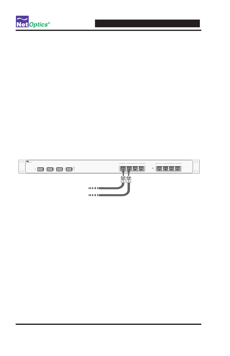
Connecting to the Network
To connect to the network:
1 . Connect Network Port 1 to the appropriate switch, server or router device
using a CAT5e RJ45 cable .
2 . Connect Network Port 2 to the appropriate switch, server or router device
using a CAT5e RJ45 cable .
Figure 4: Connecting to the Network
3 . Repeat Steps 1 and 2 for the rest of the network ports of the Link
Aggregator Tap .
4 . Verify that the Link Aggregator Tap Network Ports are cabled in-line
between two devices .
Note: ______________________________________________________________
The second power supply is available to support the flow of traffic to the
monitoring device should the first power supply fail. If the first power supply
is unavailable, the second power supply supplies all power for the Tap.
____________________________________________________________________
www.netoptics.com
In-Line Link Aggregator
Monitor
Network
LINK
ACT
LINK
ACT
LINK
ACT
LINK
ACT
1
2
3
4
2
1
A
B
A
B
4
3
A
B
A
B
LINK
ACT
1
2
To
A switch, server or router
To
B switch, server or router