PYLE Audio PT610 User Manual
Page 5
PYLE PRO PT610 Amplifier Owner’s Manual - 3
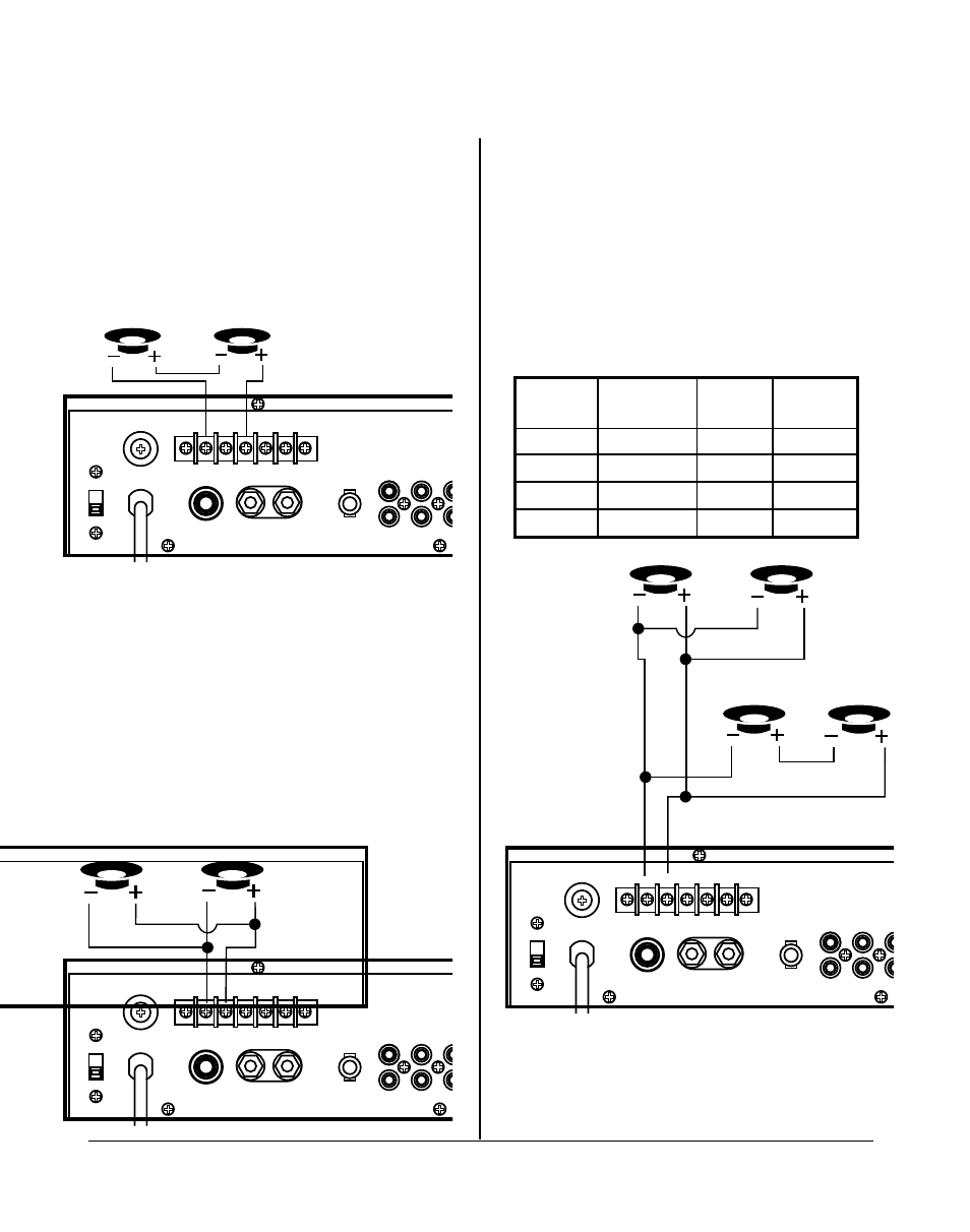
System 3: Two (or more) speakers in parallel
1. Connect the LEFT SPEAKER (-) to the RIGHT SPEAKER (-).
2. Connect both the LEFT SPEAKER (-) and the RIGHT SPEAKER
(-) to the amplifier COMMON terminal.
3. Connect the LEFT SPEAKER (+) to the RIGHT SPEAKER (+).
4. Connect both the LEFT SPEAKER (-) to the RIGHT SPEAKER
(+) to the amplifier 4 Ohm, 8 Ohm or 16 Ohm terminal,
depending on the TOTAL IMPEDANCE of the two speakers. If
each speaker has an impedance of 8 Ohms, the total speaker
impedance in this parallel configuration is 4 Ohms.
System 4: Four speakers in series/parallel combination
1. Group the four speakers in two pairs.
2. Connect one pair of speakers in series (see system 2,
above). Note total impedance in chart below.
3. Connect one pair of speakers in parallel (see system 3,
above). Note total impedance in chart below.
4. Connect the speakers’ (-) terminals to the amplifier
COMMON terminal.
5. Connect the speakers’ (+) terminals to amplifier’s 4 Ohm,
8 Ohm or 16 Ohm terminal, depending on the TOTAL
IMPEDANCE of the four speakers. See the chart below for
some sample system suggestions:
System 2: Two (or more) speakers in series
1. Connect the LEFT SPEAKER (-) to the amplifier COMMON
terminal.
2. Connect the LEFT SPEAKER (+) to the RIGHT SPEAKER (-).
3. Connect the RIGHT SPEAKER (+) to the amplifier’s 4 Ohm,
8 Ohm or 16 Ohm terminal, depending on the TOTAL
IMPEDANCE of the two speakers. If each speaker has an
impedance of 8 Ohms, the total speaker impedance in this
series configuration is 16 Ohms.
FUSE
FUSE
110
8
Ω
+
–
COM 4
Ω
8
Ω
16
Ω
70V
8
Ω
GND
IN
OUT LINE
C
THIS EXAMPLE SHOWS
8 OHM SPEAKERS, TOTAL
IMPEDANCE IS 4 OHMS
LEFT speaker
RIGHT speaker
FUSE
FUSE
110
8
Ω
+
–
COM 4
Ω
8
Ω
16
Ω
70V
8
Ω
GND
IN
OUT LINE
C
THIS EXAMPLE SHOWS
4 OHM SPEAKERS, TOTAL
IMPEDANCE IS 8 OHMS
LEFT speaker
RIGHT speaker
FUSE
FUSE
110
8
Ω
+
–
COM 4
Ω
8
Ω
16
Ω
70V
8
Ω
GND
IN
OUT LINE
C
PARALLEL
LEFT speaker
PARALLEL
RIGHT speaker
SERIES
LEFT speaker
SERIES
RIGHT speaker
NOTE:
This diagram is
for THE FIRST THREE
examples
in chart.
In this case, 4 Ohm
terminal is used.
Your system
impedance may vary
depending on the
impedances of
the individual
speakers, and may
require hookup to
the 8 or 16 Ohm
terminals.
PARALLEL
speaker pair
(net impedance
for pair)
SERIES
speaker pair
(net impedance
for pair)
TOTAL
IMPEDANCE
in this type
system
Use this
amp
terminal
8
Ω ∗
8
Ω
∗
4
Ω∗
16
Ω ∗
16
Ω
∗
32
Ω∗
3.∗Ω
4
Ω
16
Ω ∗
16
Ω
∗
8
Ω∗
4
Ω ∗
4
Ω
∗
8
Ω∗
∗Ω
4
Ω
16
Ω ∗
16
Ω
∗
8
Ω∗
8
Ω ∗
8
Ω
∗
16
Ω∗
∗.∗Ω
8
Ω
8
Ω ∗
8
Ω
∗
4
Ω∗
8
Ω ∗
8
Ω
∗
16
Ω∗
3.∗Ω
4
Ω
NOTE: ADDITIONAL SPEAKERS MAY BE INCLUDED IN SERIES, BUT IT IS NECESSARY
TO CALCULATE TOTAL IMPEDANCE, AND CONNECT THE SPEAKER CIRCUIT TO
A TERMINAL OF APPROPRIATE IMPEDANCE. FOR EXAMPLE, IF THREE SPEAKERS
OF 4 OHMS ARE USED, TOTAL IMPEDANCE IS 12 OHMS – YOU SHOULD CONNECT
TO THE 16 OHM TERMINAL.
Although the description above is for combining a series pair and a parallel pair
in a parallel hookup, you may also elect to combine two series pairs in a parallel
hookup. Simply be sure you have properly calculated the total impedance, and
attach the (+) speaker circuit wire to the proper amp terminal. For example, if
you use two pairs of 8 Ohm speakers in series each pair, the impedance for each
pair is 16 Ohms. Connected in parallel to the amp terminals, the TOTAL impedance
is 8 Ohms, so you should connect these to the 8 Ohm terminal.
Series/parallel variations