Pvi firepower – PVI Industries FIREPOWER B40 User Manual
Page 7
PV500-22A 08-98
7
Section 22A
PVI FIREPOWER
TWO STAGE B SERIES OIL BURNER ADJUSTMENTS
AIR ADJUSTMENT
First stage: Set the operating switch on low capacity. Loosen the screw (A) and
move the damper arm (C) along the scale (E) to a position where the flame does
not soot nor blow out. Tighten the screw.
Second stage: The operating switch remains on low capacity. Screw the knurled
ring (B) by means of an adjustment pin in (reduce) or out (increase). The position
of the damper can be read on the damper scale (E).
Check the air adjustments of the second stage by making a flue gas analysis.
Figure 22A-5
ADJUSTMENT & REMOVAL OF NOZZLE ASSEMBLY
To adjust nozzle assembly (C), loosen screw
(D) and move the nozzle forward or retract by
turning the adjustment screw (E). Line up the
pointer on the locating block to the index
position specified in Table 22-2 (pg. 9) for best
results.
To remove the nozzle, remove the burner
cover and disconnect the electrode cables.
Separate the nozzle assembly from the fan
housing by loosening the connecting pipe (F)
and extracting the connecting pipe from the
nozzle port. Then disconnect the 2nd stage oil
line from the fitting located on the inside of the
fan housing.
Figure 22A-6
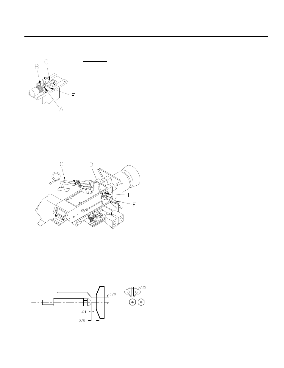
IGNITION ELECTRODE ADJUSTMENT
Check that the measurements between the
nozzle, the ignition electrodes and the
pressure plate correspond to Figure 22-7.
Figure 22A-7