Assembly / bringing into use, Attaching the feet, See fig. b) – Parkside PDKS 120 User Manual
Page 10: Attaching the dust blow tube, See fig. c), Bringing into use, Setting the stroke rate, Tilting the saw table, See figs. d, e), Inserting / removing the saw blade
10 GB/IE/CY
Q
Attaching the feet
12
(see Fig. B)
j
Attach the feet
12
from below through the
mounting holes in the device‘s base plate.
j
Place the plain washers and then the nuts on to
the screw threads.
j
Tighten the nuts using a size 10 open spanner.
Q
Attaching the dust blow tube
1
(see Fig. C)
j
Screw the dust blow tube
1
clockwise into the
opening provided for it.
Q
Bringing into use
Take note of the mains voltage. The mains voltage
at the mains socket must match that shown on the
rating plate on the device. Devices marked with
230 V can also be operated at 220 V.
CAUTION! Make sure that the device is
switched off before you connect it to the mains supply.
J
Always switch on the electrical power tool before
moving the workpiece against it. Otherwise
there is the risk of kickback.
Setting up the device:
j
Grab the device at the position labelled “Bitte
hier anheben - Please lift here” to position the
device.
Switching on the device:
j
Press the green ON button
4
.
Switching off the device:
j
Press the red OFF button
3
.
Q
Setting the stroke rate
j
Turn the stroke rate controller
2
clockwise to
increase the stroke rate.
j
Turn the stroke rate controller
2
anticlockwise
to decrease the stroke rate.
NOTE: Be aware that too high a stroke rate leads
to the saw blade heating up, an increase in wear
of the saw blade and burn marks on the material.
j
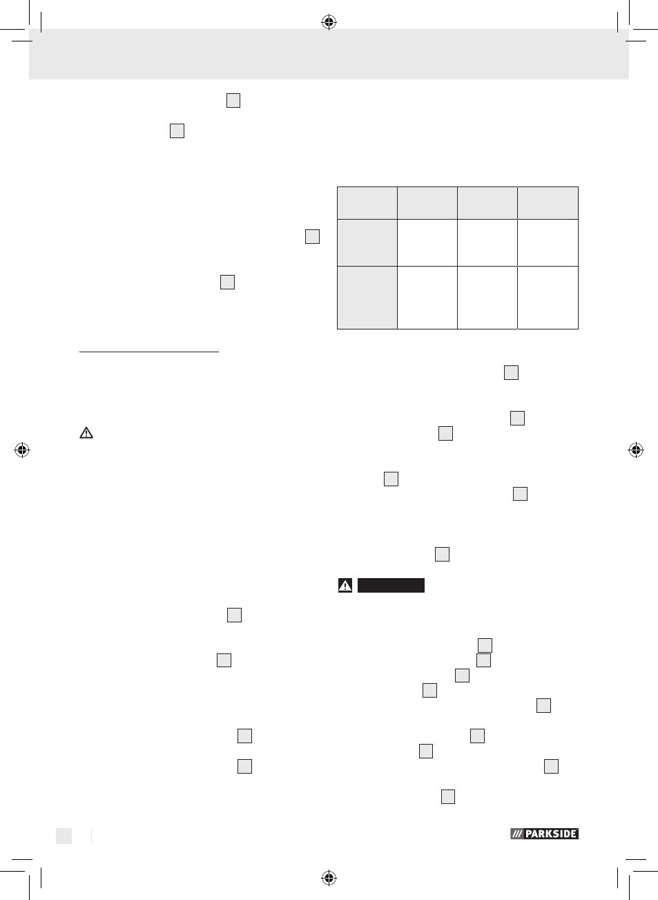
Select a saw speed suitable for the material
being sawn.
Maximum
speed
Medium
speed
Minimum
speed
Thick woo-
den board
Straight
cut
Normal
fretsaw
work
-
Thin woo-
den or
plastic
board
Straight
and curved
cuts
Normal
and intrica-
te fretsaw
work
Intricate
fretsaw
work
Q
Tilting the saw table
6
(see Figs. D, E)
j
Unscrew the angle setting screw
5
.
j
Tilt the saw table
6
until the desired is
reached.
NOTE: The angle can be read off the angle
scale
6 a
.
j
Retighten the angle setting screw
5
.
Q
Inserting / removing the
saw blade
7
WARNING!
DANGER OF INJURY!
Pull the mains plug out of the socket before you
carry out any task on the device,
Inserting the saw blade
7
:
j
Lift up the clamping lever
13
.
j
Insert the saw blade
7
through the opening in
the saw table
6
.
Ensure that the teeth of the saw blade
7
point
forwards and downwards.
j
Suspend the saw blade
7
in the bottom
blade mount
14
.
j
Then hook the top pin of the saw blade
7
in
the recess provided for this purpose in the top
saw blade mount
8
.
Assembly / Bringing into use
33383_SCROLL SAW_Dekupiersaege_Content_LB6.indd 10
23.07.09 11:29