Sgnd & frgnd (jb4), Model im2rc/ia (10base-t ethernet rear card), Status – Patton electronic 2073RC User Manual
Page 15
15
SGND & FRGND (JB4).
In the connected position, this strap links DB-15
pin 8 (Signal Ground) and frame ground through a 100 ohm resistor. In
the open position, pin 8 is connected directly to frame ground
(see Table 6).
Model IM2RC/IA (10Base-T Ethernet Rear Card)
There are no jumpers to set in the Model IM2RC/IA, for more informa-
tion, refer to the Model IM2RC/IA user manual
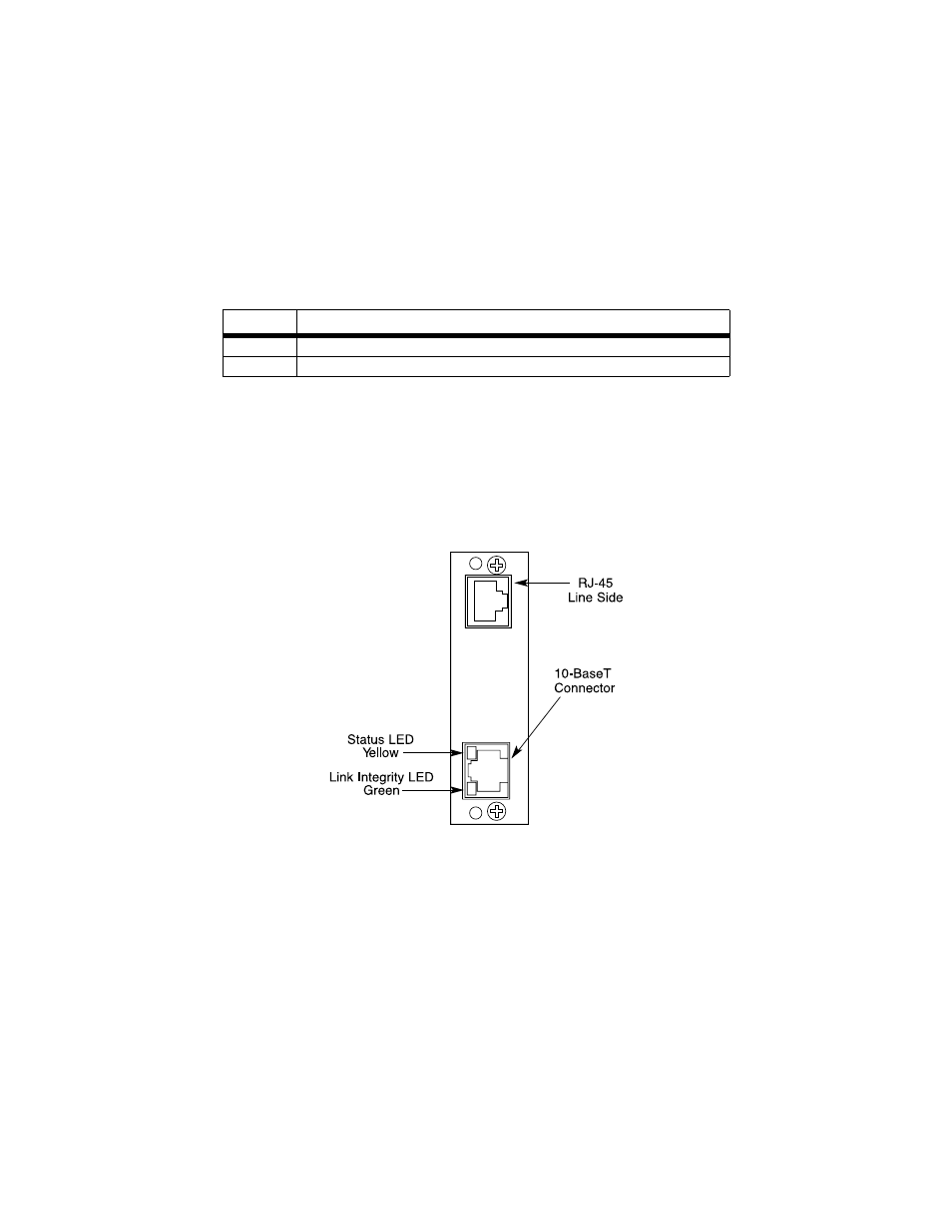
The Model IM2RC/IA provides line side connections through an RJ-45
connector. Figure 7 shows rear panel options and connectors locations.
Descriptions of the 10Base-T connector LEDs follow Figure 7.
Figure 7.
IM2RC/A, rear panel options
Status.
Blinks yellow from one to eleven times to indicate system status.
Each pulse pattern is separated by a 2 second “off” period. Greater
pulse patterns have higher priority (buffer saturation has greater priority
than an empty MAC table). Valid system statuses are:
• 1 pulse = system status ok
• 2 pulses = No MAC entries in the MAC address table
• 3 pulses = Clear to send (CTS) or Carrier Detect (DCD) from base unit
are not asserted
Table 6:
JB4 strap settings
Position
Description
1 & 2
SGND (Pin 8) and FRGND Connected through a 100 ohm resistor
2 & 3
SGND (Pin 8) and FRGND Directly Connected