Hookup – Polk Audio LC80i-IP User Manual
Page 6
For more information visit our website at www.polkaudio.com 41
40
Polk Audio Customer Service: 1-800-377-7655 (Outside US & Canada: 410-358-3600) Monday-Friday, 9:00 AM-6:00 PM EST, [email protected]
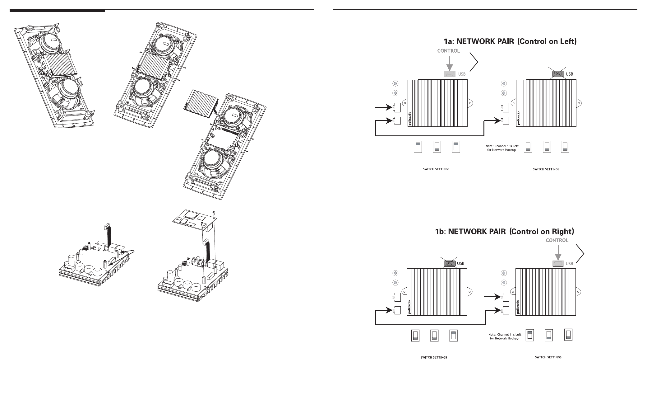
Hookup
OPTIONAL
CHANNEL 1
CHANNEL 2
NETWORK IN
COMM
CHANNEL 1
CHANNEL 2
NETWORK IN
COMM
CONTROL
CFG
CHANNEL
Y
N
A
B
1
2
CONTROL
CFG
CHANNEL
Y
N
A
B
1
2
1
2
3
4
5
Disconnect all cables.
Disconnect all cables.
Disconnect all cables.
Disconnect all cables.
Disconnect all cables.
Disconnect all cables.
Remove the (4) Torx screws (size T-10) holding the heat
sink to the amp housing. Set the screws safely aside.
Remove the (4) Torx screws (size T-10) holding the heat
sink to the amp housing. Set the screws safely aside.
Remove the (4) Torx screws (size T-10) holding the heat
sink to the amp housing. Set the screws safely aside.
Remove the (4) Torx screws (size T-10) holding the heat
sink to the amp housing. Set the screws safely aside.
Remove the (4) Torx screws (size T-10) holding the heat
sink to the amp housing. Set the screws safely aside.
Remove the (4) Torx screws (size T-10) holding the heat
sink to the amp housing. Set the screws safely aside.
Disconnect the ribbon cable from the
break-out board. Remove the amplifier
and loose cables from the amp housing.
Disconnect the ribbon cable from the
break-out board. Remove the amplifier
and loose cables from the amp housing.
Disconnect the ribbon cable from the
break-out board. Remove the amplifier
and loose cables from the amp housing.
Disconnect the ribbon cable from the
break-out board. Remove the amplifier
and loose cables from the amp housing.
Disconnect the ribbon cable from the
break-out board. Remove the amplifier
and loose cables from the amp housing.
Disconnect the ribbon cable from the
break-out board. Remove the amplifier
and loose cables from the amp housing.
Turn the amplifier over and remove the two screws
from the two metal standoffs located on the PCB.
Turn the amplifier over and remove the two screws
from the two metal standoffs located on the PCB.
Turn the amplifier over and remove the two screws
from the two metal standoffs located on the PCB.
Turn the amplifier over and remove the two screws
from the two metal standoffs located on the PCB.
Turn the amplifier over and remove the two screws
from the two metal standoffs located on the PCB.
Turn the amplifier over and remove the two screws
from the two metal standoffs located on the PCB.
Install the network decoder card on the standoffs, mating the
two sides of the 40-pin connector. Press down and ensure that
the card snaps onto the two plastic standoffs.
Install the network decoder card on the standoffs, mating the
two sides of the 40-pin connector. Press down and ensure that
the card snaps onto the two plastic standoffs.
Install the network decoder card on the standoffs, mating the
two sides of the 40-pin connector. Press down and ensure that
the card snaps onto the two plastic standoffs.
Install the network decoder card on the standoffs, mating the
two sides of the 40-pin connector. Press down and ensure that
the card snaps onto the two plastic standoffs.
Install the network decoder card on the standoffs, mating the
two sides of the 40-pin connector. Press down and ensure that
the card snaps onto the two plastic standoffs.
Install the network decoder card on the standoffs, mating the
two sides of the 40-pin connector. Press down and ensure that
the card snaps onto the two plastic standoffs.
6
Secure the network decoder card by reinserting the
two standoff screws into the two metal standoffs.
Secure the network decoder card by reinserting the
two standoff screws into the two metal standoffs.
Secure the network decoder card by reinserting the
two standoff screws into the two metal standoffs.
Secure the network decoder card by reinserting the
two standoff screws into the two metal standoffs.
Secure the network decoder card by reinserting the
two standoff screws into the two metal standoffs.
Secure the network decoder card by reinserting the
two standoff screws into the two metal standoffs.
7
Reinstall the amplifier onto the amplifier
chassis (reversing steps 1, 2 & 3).
Reinstall the amplifier onto the amplifier
chassis (reversing steps 1, 2 & 3).
Reinstall the amplifier onto the amplifier
chassis (reversing steps 1, 2 & 3).
Reinstall the amplifier onto the amplifier
chassis (reversing steps 1, 2 & 3).
Reinstall the amplifier onto the amplifier
chassis (reversing steps 1, 2 & 3).
Reinstall the amplifier onto the amplifier
chassis (reversing steps 1, 2 & 3).
OPTIONAL
CHANNEL 1
CHANNEL 2
NETWORK IN
COMM
CHANNEL 1
CHANNEL 2
NETWORK IN
COMM
CONTROL
CFG
CHANNEL
Y
N
A
B
1
2
CONTROL
CFG
CHANNEL
Y
N
A
B
1
2
Hookup
standoffs