Panasonic BM-ET500 User Manual
Page 13
13
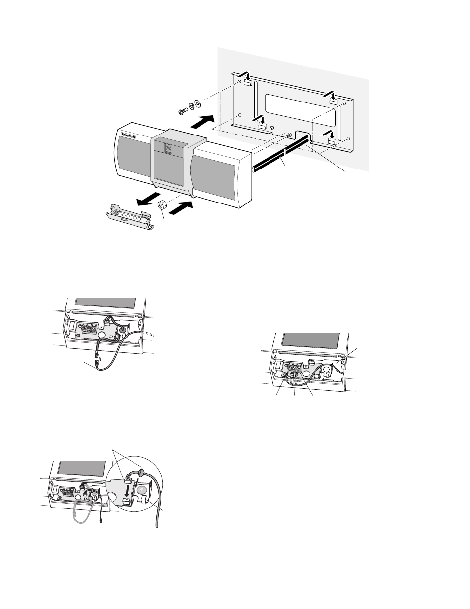
4. Attach the unit to the mounting bracket.
You need to make a hole of approx. ø 30 mm on the wall to pass the cables out of the rear side.
5. Connect the coaxial cable to the unit.
The unit is connected to the control unit (Camera 1 - 3).
6. When you use the built-in CCTV camera, connect the
supplied video output cable to VIDEO OUT. Then, con-
nect the supplied video output cable and the video
input cable of a connected device (for example, a mon-
itor or DVR).
7. Connect the DC power cable to the unit.
If you use power supply from the control unit to the unit,
connect the DC power cable to 0 V and +32 V ports.
If you use 24 V DC power supply from an external
power supply device, connect the power cable to 0 V
and +24 V ports.
Caution: Take DC 24 V power supply from a third-party
external power supply device that complies with the
safety standard. (Refer to p.21.)
8. Attach the numeric keyboard.
Connect the control cable which has been connected
to the numeric keyboard. Then, attach the keyboard
with the tamperproof screws.
Caution: Insert the cable into the unit so as to avoid
pressure from the keyboard.
1
2
3
4
5
CANCEL
Screw nut (M5)
(1) Attach the mounting
bracket to the wall.
(2) Remove the
numeric keyboard.
(3) Remove the shipping lock.
(4) Attach the unit to the mounting bracket.
Secure the unit and bracket with the screw nut,
using an 8 mm {0.03 in.} socket driver.
(5) Connect the cables to the unit.
(6) Attach the numeric keyboard.
*Refer to the control unit’s operating instructions
for the specifications.
Coaxial cable and
DC power cable *
(from the control unit)
Provide access for
cables to be routed
through the wall.
Coaxial cable
To CAMERA 1 - 3 of the control unit
To a monitor or digital disk recorder
Connect them.
Pass the cable
through this hole.
0 V
+32 V
+24 V
Pass the cable
through this hole.
To the control unit