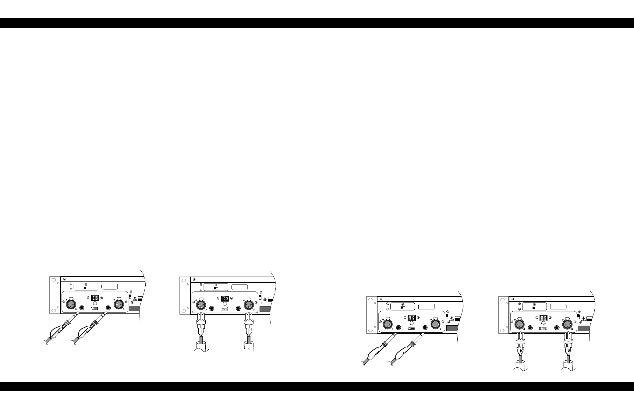
Installation, Figure 4a figure 4b 6, R m s – Phoenix Gold pm1400 User Manual
Page 9
pm1400: 6.7 amps for 120V versions, 3.5 amps for 230V versions
(see your Carver Professional dealer for information on Carver Professional Accessories)
Input Sensitivity
The input sensitivity of the amplifiers are set at the factory to 1.5V
for rated output. The input sensitivity can
by adding two jumpers on the Main Amplifier Board. See page 12 of this owner’s manual
7
TO REDUCE THE RISK OF FIRE OR ELECTRIC SHOCK,
DO NOT EXPOSE THIS EQUIPMENT TO RAIN OR MOISTURE.
RISK OF HAZARDOUS ENERGY! MAKE PROPER
SPEAKER CONNECTIONS. SEE OPERATING
MANUAL BEFORE USING.
INPUT IMPEDANCE 25K OHMS EACH LEG TO GROUND (TOTAL 50K OHMS BALANCED)
TO REDUCE THE RISK OF FIRE OR ELECTRIC SHOCK,
DO NOT EXPOSE THIS EQUIPMENT TO RAIN OR MOISTURE.
RISK OF HAZARDOUS ENERGY! MAKE PROPER
SPEAKER CONNECTIONS. SEE OPERATING
MANUAL BEFORE USING.
INPUT IMPEDANCE 25K OHMS EACH LEG TO GROUND (TOTAL 50K OHMS BALANCED)
6
Installation
Location and General Precautions
Observe the following precautions when choosing a location for your amplifier.
A. Do not expose the unit to rain or moisture. If a fluid or foreign object should enter the unit, disconnect
the power plug and contact an authorized dealer or service center. Do not pull out the plug by pulling on the
cord; grasp the plug firmly.
B. Protect from heat and allow adequate ventilation. Place away from direct sources of heat, such as heating
vents and radiators. All components produce some heat during operation, so make sure that the ventilation
holes are not covered and that air is allowed to circulate freely behind, beside and above the unit. Excessive heat is the
single greatest source of both short-term and long-term component failure.
Mechanical Considerations
The pm1400 requires two rack space units (3.5”) and a depth of 15” inside the rack, including the rear supports. Secure
the unit mechanically using four screws with washers to prevent marring the front panel. Neoprene rubber washers are
a good choice because they grip the screw head and prevent them from backing out when vibrated or transported.
Rear Support for Road Applications
If the pm1400 is rack-mounted and the rack is transported, mechanical support for the rear of the amplifier is required.
This could take the form of a shelf across the rear of the amplifier or brackets that engage the rear of the unit. This
practice is recommended for all electronic instruments.
Thermal Considerations
When the pm1400 is used free-standing, no thermal considerations are necessary other than keeping the ventilation
holes open. If the amplifiers are rack-mounted, ensure that adequate ventilation exists in front of and behind the
amplifier. When several amplifiers are mounted together in a rack, you may need to provide air inlets from the outside
of the rack. The pm1400 is fan cooled. The fan is internally mounted so that it draws air in from the front and exhausts
it out the rear. This allows cool air from outside the amplifier to flow over and cool the power supply components
located in front of the heatsinks before being warmed by the heat-producing output devices, thus providing optimum
cooling efficiency. The pm1400 may be stacked directly on top of other amplifiers without spacer panels. If the
amplifiers are used with other amplifiers, ensure that the heat output from the other amplifiers doesn’t interfere with the
ventilation of the pm1400 (or vice versa).
TO REDUCE THE RISK OF FIRE OR ELECTRIC SHOCK,
DO NOT EXPOSE THIS EQUIPMENT TO RAIN OR MOISTURE.
WARNING
MADE
IN
USA
+
–
GND
FOR BRIDGED
OPERATIONS CONSULT
OWNER'S MANUAL
RISK OF HAZARDOUS ENERGY! MAKE PROPER
SPEAKER CONNECTIONS. SEE OPERATING
MANUAL BEFORE USING.
WARNING
1
2
3
+
Serial Number
1
2
3
PUSH
1
2
3
PUSH
INPUT IMPEDANCE 25K OHMS EACH LEG TO GROUND (TOTAL 50K OHMS BALANCED)
SEQUENCE
SND RCV
ON
CAUTION
A
RISQUE DE CHOC ELECTRIQUE
RISK OF ELECTRIC SHOCK
DO NOT OPEN
CLIPPING
ELIMINATOR
OFF
ON
OFF
LEVEL DEFEAT
RING
–
TIP
+
SLEEVE
(Shield)
From
Channel 2
RING
–
TIP
+
SLEEVE
(Shield)
From
Channel 1
TO REDUCE THE RISK OF FIRE OR ELECTRIC SHOCK,
DO NOT EXPOSE THIS EQUIPMENT TO RAIN OR MOISTURE.
WARNING
MADE
IN
USA
+
–
GND
FOR BRIDGED
OPERATIONS CONSULT
OWNER'S MANUAL
RISK OF HAZARDOUS ENERGY! MAKE PROPER
SPEAKER CONNECTIONS. SEE OPERATING
MANUAL BEFORE USING.
WARNING
1
2
3
+
Serial Number
1
2
3
PUSH
1
2
3
PUSH
INPUT IMPEDANCE 25K OHMS EACH LEG TO GROUND (TOTAL 50K OHMS BALANCED)
SEQUENCE
SND RCV
ON
CAUTION
ATTENTION
RISQUE DE CHOC ELECTRIQUE
NE PAS OUVRIR
RISK OF ELECTRIC SHOCK
DO NOT OPEN
CLIPPING
ELIMINATOR
OFF
ON
OFF
LEVEL DEFEAT
–
+
GND
(Shield)
–
+
GND
(Shield)