Connections, Connecting to the aerial, Connections to your tv – Porter-Cable DVDR630VR User Manual
Page 16: Rf coaxial connection, Scart connection, S-video connection, Component video connection, Progressive scan (colorstream, Pro) connection, Audio (left/right) connection
16
Connections
ips
Depending on your TV and other equipment you wish
to connect, there are various ways you could connect
the recorder. Use only one of the connections
described below.
Please refer to the manuals of your TV, VCR, Stereo
System or other devices as necessary to make the
best connections.
Caution
– Make sure the Recorder is connected directly to the
TV. Tune the TV to the correct video input channel.
– Do not connect the Recorder’s AUDIO OUT jack to
the phono in jack (record deck) of your audio system.
– Do not connect your Recorder via your VCR. The
DVD image could be distorted by the copy protection
system.
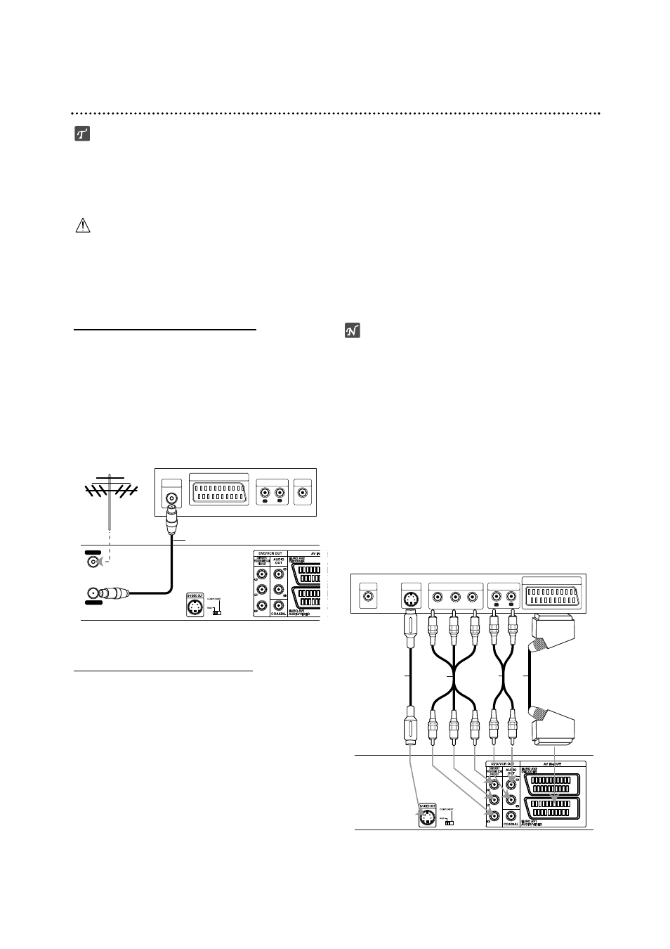
Connecting to the Aerial
Remove the aerial cable plug from your TV set and
insert it into the aerial socket at the back of the
recorder. Plug one end of the aerial cable into the TV
socket on the recorder and the other end into the aerial
input socket on your TV set.
RF coaxial connection
Connect the RF. OUT jack on the Recorder to the aerial
input jack on the TV using the 75-ohm Coaxial Cable
supplied (R). The RF. OUT jack passes the signal
through from the AERIAL jack.
Connections to Your TV
Make one of the following connections, depending on
the capabilities of your existing equipment.
When using the COMPONENT VIDEO OUT jacks,
set the VIDEO OUTPUT switch to COMPONENT.
When using the SCART jack, set the VIDEO OUT-
PUT switch to RGB.
SCART connection
Connect the EURO AV1 AUDIO/VIDEO scart jack on
the Recorder to the corresponding in jacks on the TV
using the scart cable (T).
S-Video connection
Connect the S-VIDEO OUT jack on the Recorder to the
S-Video in jack on the TV using the S-Video cable (S).
Component Video connection
Connect the COMPONENT/PROGRESSIVE SCAN
VIDEO OUT jacks on the Recorder to the correspon-
ding input jacks on the TV using an Y Pb Pr cable (C).
Progressive Scan (ColorStream
®
Pro) connection
If your television is a high-definition or “digital ready” tel-
evision, you may take advantage of the recorder’s pro-
gressive scan output for the highest video resolution
possible. If your TV does not accept the Progressive
Scan format, the picture will appear scrambled if you try
Progressive Scan on the recorder.
Connect the COMPONENT/PROGRESSIVE SCAN
VIDEO OUT jacks on the Recorder to the correspon-
ding input jacks on the TV using an Y Pb Pr cable (C).
otes
– Set the Progressive to “ON” on the setup menu for
progressive signal, see page 24.
– Set the progressive to “Off” by removing any disc
from the unit and close the disc tray. Then press
STOP and hold it for five seconds before releasing it.
– Progressive scan does not work with the analog video
connections or S-VIDEO connection.
Audio (Left/Right) Connection
Connect the left and right AUDIO OUT jacks of the
Recorder to the audio left and right IN jacks on the TV
using the audio cables (A). Do not connect the
Recorder’s AUDIO OUT jack to the phono in jack
(record deck) of your audio system.
Aerial
Rear of Recorder
R
Rear of TV
ANTENNA
INPUT
L
R
AUDIO INPUT
VIDEO
INPUT
SCART INPUT
AERIAL
RF.OUT
L
R
AUDIO INPUT
VIDEO
INPUT
S-VIDEO
INPUT
SCART INPUT
Pr
Pb
Y
COMPONENT VIDEO INPUT
Rear of Recorder
Rear of TV
S
A
T
C