Powermatic PM2000 User Manual
Page 17
17
Precision Miter Gauge
Setting the miter gauge angle
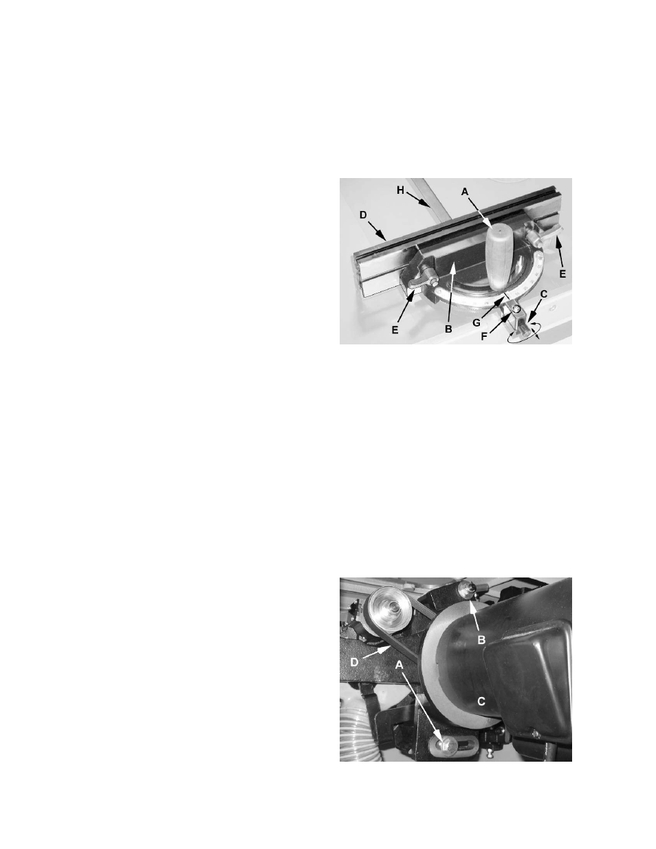
Referring to Figure 15:
The precision miter gauge has a rack and pinion
adjustment for setting the angle. To operate:
1. Slide the miter gauge into one of the slots on
the table top.
2. Loosen
lock handle (A).
To adjust the body (B) of the miter gauge to the
desired angle:
3. Pull the spring-loaded knob (C) out and turn
until the body (B) of the miter gauge is at the
desired angle as indicated on the scale.
4. Tighten
the
lock handle (A).
Indent settings
There are indents at the 0º, 30º and 45º right and
left positions. At these settings, release the
knob (C) to engage the stop rod. Then tighten the
lock handle (A).
Note: Do not rely solely on the indents for an
accurate setting. After the stop rod engages at the
0º, 30º and 45º positions, make a fine adjustment
with the knob (C), if necessary, setting it against
the scale indicator.
Extension plate
The extension plate (D) can be adjusted by sliding
to the right or left or removed entirely.
To adjust – loosen two lock handles (E), position
the extension plate and tighten the lock handles.
To remove – slide the extension plate completely
off and remove the lock handles (E) and mounting
hardware.
Calibrating the miter gauge
1. Place the miter gauge in one of the slots (H) on
the table top.
2. Set the miter gauge to 90º (0º setting on the
scale) by loosening the lock handle (A), then
pulling the spring-loaded knob (C) out and
turning the body (B) until 0º is indicated on the
scale (F).
3. Measure the accuracy of the gauge against the
slot with a combination square.
If adjustment is necessary:
4. Adjust
the
body (B) until it is perfectly square
(90º) to the miter slot (H).
5. Tighten
the
lock handle (A).
6. Verify that the scale indicator (G) reads 0º. If
further adjustment is necessary:
7. Loosen the screw (F) and adjust the indicator
(G) until it reads 0º.
8. Tighten the screw (F).
NOTE: The bar of the miter gauge has a slot with
two set screws. Adjust these set screws to
eliminate any play between bar and miter slot.
Figure 15
Drive Belt
The saw is equipped with a poly-V belt.
Referring to Figure 16:
To adjust the belt tension – loosen the hex nut
(B) on the motor pivot and hex cap screw (A) on
the bracket with a 19mm socket or wrench. Pivot
the motor (C) and bracket to the right to increase
the belt tension. Retighten both screws (A, B).
To remove and replace belt – loosen the hex
nut (B) on the motor pivot and hex cap screw (A)
on the bracket with a 19mm socket or wrench.
Pivot the motor (C) and bracket to the left as far as
possible. Remove the old poly-V belt (D) and
replace. Adjust belt tension as described above.
Figure 16