Back of the unit, The symbols on your dvd recorder display – Philips DVDR75/021 User Manual
Page 6
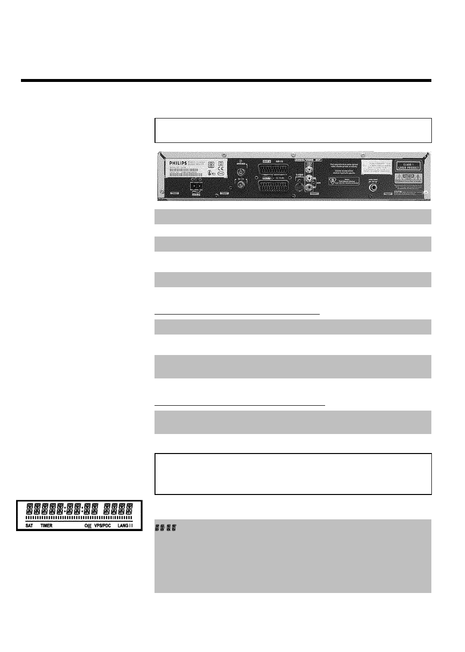
Back of the unit
4MAINS
Mains socket: Connection to the mains supply (230V/50Hz)
ANTENNA IN
Aerialinput: Connection of the aerial
TV OUT
Aerialoutput: Connection of the TV set
EXT 2 AUX-I/O
Scart socket 2: Connection of an additional device (satellite receiver,
set-top box, video recorder, camcorder, etc.)
EXT 1 TO TV-I/O
Scart socket 1: Connection of a TV set. RGB output
Output sockets (AUDIO/VIDEO OUT)
OUT S-VIDEO (Y/C)
S Video output: Connection of an S-Video-compatible TV set
OUT VIDEO
(CVBS)
Video output (yellow socket): Connecting a TV set with a video
input (CVBS, Composite Video)
OUT L AUDIO R
Analogue audio output (white/red socket): Connection of a TV
set with audio input sockets or connection of an additional device
Output socket (DIGITAL AUDIO OUT)
DIGITAL AUDIO
OUT
Digitalaudio output: Connection of a digital audio device
(amplifier/receiver)
The symbols on your DVD recorder
display
These symbols can light up on your DVD recorder display:
Multi-function display/text line
•) Clock
•) Disc/title playing time
•) OTR switch-off time
•) Title name
•) Display of the programme number of the TV channel/playing
time/channel name/function.
•) Display of information and alerts