Service and adjustments, Tractor – Poulan 186914 User Manual
Page 19
19
SERVICE AND ADJUSTMENTS
TRACTOR
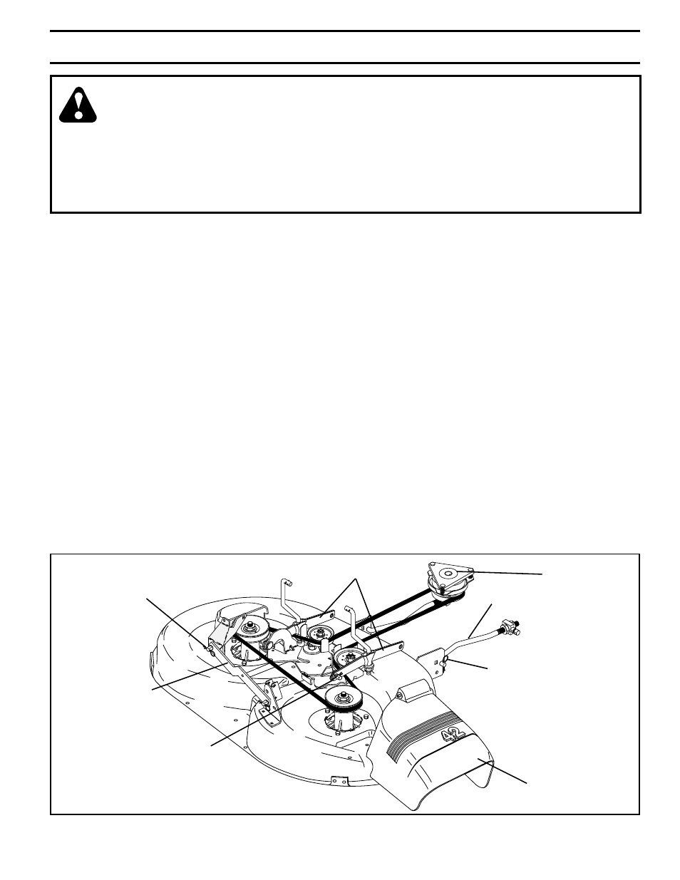
FIG. 18
01
698
RETAINER
SPRINGS
(BOTH SIDES)
RE TAIN ER SPRINGS
(BOTH SIDES)
ELECTRIC CLUTCH
PULLEY
FRONT LINK
SUS PEN SION ARMS
RETAINER
SPRING
ANTI-SWAY BAR
TO REMOVE MOWER (See Fig. 18)
Mower will be easier to remove from the right side of tractor.
• Place attachment clutch switch in “DISENGAGED”
po si tion.
• Move attachment lift lever forward to lower mower to
its lowest position.
• Roll belt off electric clutch pulley.
• Disconnect anti-sway bar from chassis bracket by
re mov ing re tain er spring.
• Disconnect suspension arms from rear deck brackets
by removing retainer springs.
• Disconnect front links from deck by removing retainer
springs.
• Raise lift lever to raise suspension arms. Slide mower
out from under tractor.
IMPORTANT: If an attachment other than the mower deck
is to be mounted on the tractor, remove the front links.
TO INSTALL MOWER (See Fig. 18)
• Raise attachment lift lever to its highest position.
• Slide mower under tractor with defl ector shield to right
side of tractor.
• Lower lift lever to its lowest position.
DEFLECTOR SHIELD
• Connect front links to mower deck and secure with
retainer springs..
• Connect suspension arms to rear deck brackets and
secure with retainer springs.
• Connect anti-swaybar to chassis bracket and secure
with retainer spring.
• Install belt into electric clutch pulley groove.
WARNING: TO AVOID SERIOUS INJURY, BEFORE PERFORMING ANY SER
VICE OR AD
JUST -
MENTS:
•
Depress clutch/brake pedal fully and set parking brake.
•
Place motion control lever in neutral (N) position.
•
Place attachment clutch in “DISENGAGED” position.
•
Turn ignition key to “STOP” and remove key.
•
Make sure the blades and all moving parts have completely stopped.
•
Disconnect spark plug wire from spark plug and place wire where it cannot come in contact
with
plug.
TO LEVEL MOWER HOUSING
Adjust the mower while tractor is parked on level ground
or driveway. Make sure tires are properly infl ated (See
“PROD UCT SPECIFICATIONS” section of this manual). If
tires are over or underinfl ated, you will not properly adjust
your mower.
SIDE-TO-SIDE ADJUSTMENT (See Figs. 19 and 20)
• Raise mower to its highest position.
• At the midpoint of both sides of mower, measure height
from bot tom edge of mower to ground. Distance “A”
on both sides of mower should be the same or within
1/4" of each other.
• If adjustment is necessary, make adjustment on one
side of mower only.
• To raise one side of mower, tighten lift link ad just ment
nut on that side.
• To lower one side of mower, loosen lift link ad just ment
nut on that side.