Pentair IC20 User Manual
Page 12
4
IntelliChlor Electronic Chlorine Generator Installation and User’s Guide
Loop Plumbing Diagram
The IntelliChlor Electronic Chlorine Generator is designed to operate with water flow rates from 20 gallons per
minute (gpm) up to 105 gpm. Do not exceed 105 gpm or pipe manufacturers recommended flow rate,
whichever is less. For flow rates over 80 gpm, it is recommend that you use a bypass loop (as shown below)
for best chlorine production. Installations with flow rates over 80 gallons per minute are those that have
in-floor cleaning systems or booster pumps. These systems should use a bypass loop with the IECG with a
flow control valve that assures that the flow through the IECG is maintained within its designed operating
water flow rates.
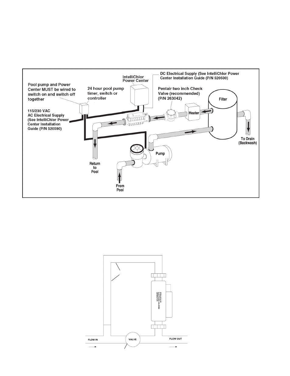
System Schematic Diagram
The following schematic diagram shows a typical IntelliChlor system installation. It is recommended that a 2
inch check valve be installed between the input side of the IntelliChlor Electronic Chlorine Generator and the
main heater output pipe, as shown below. Note: This schematic diagram is not drawn to scale. Refer to the
relevant portions of this Installation and User’s Guide for information regarding proper placement and
spacing of all equipment depicted in this diagram.
Flow control valve
NOT TO SCALE
Bypass loop
NOT TO SCALE