Matrix equations, C-bus controlled yuv/rgb switch tda8443a – Philips TDA8443A User Manual
Page 6
1995 Mar 07
6
Philips Semiconductors
Product specification
I
2
C-bus controlled YUV/RGB switch
TDA8443A
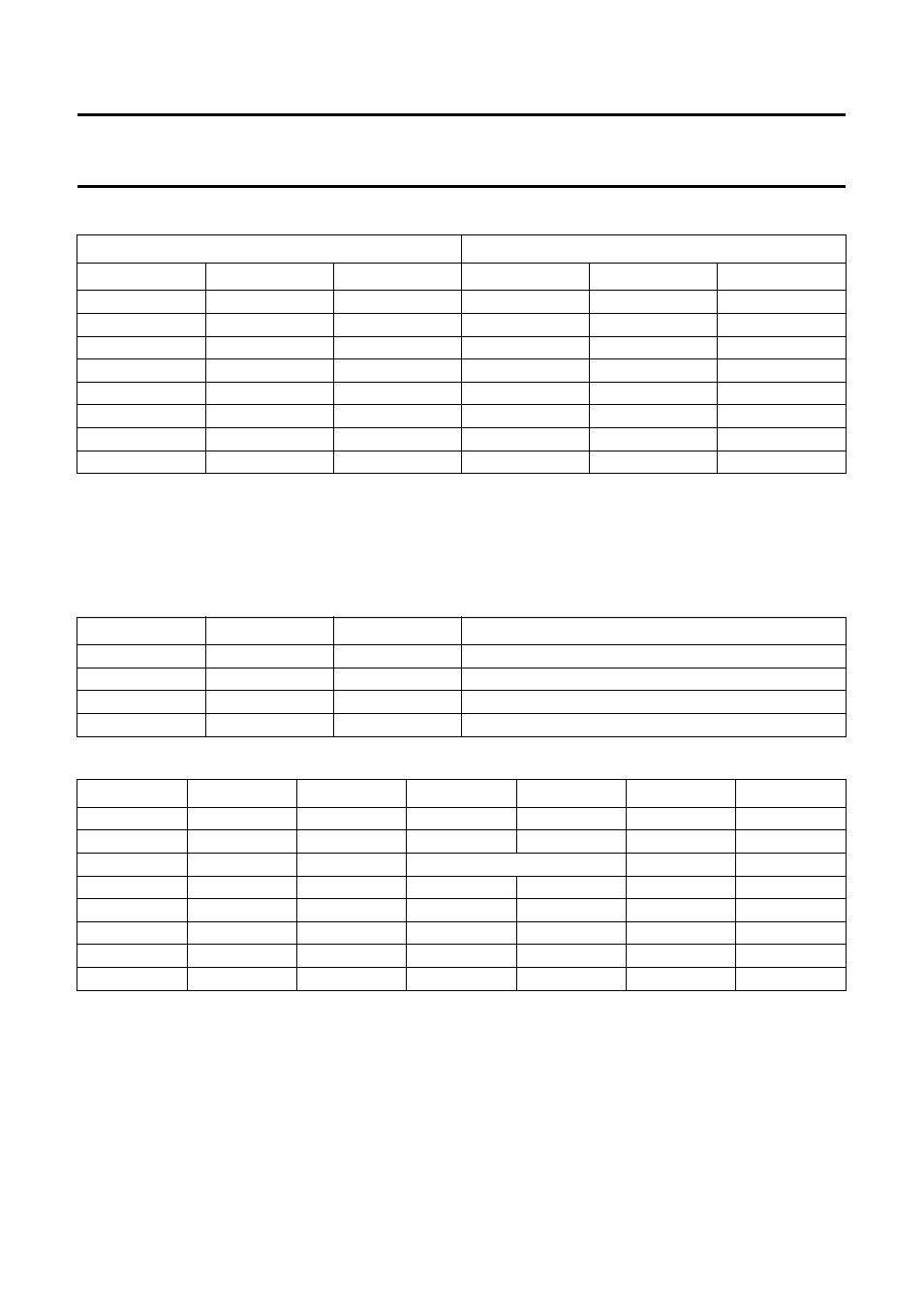
Table 2
Address selection
Notes
1. L = LOW level input voltage.
2. H = HIGH level input voltage.
3.
∗
= non-I
2
C-bus operation.
Table 3
Mode control bits D7 and D6
Table 4
Gain setting (see also Table 9)
Matrix equations
The relationship between output and input signals of the matrix is as follows:
Y = 0.3R + 0.59G + 0.11B
R
−
Y = 0.7R
−
0.59G
−
0.11B
B
−
Y =
−
0.3R
−
0.59G + 0.89B
ADDRESS SELECT PINS
(1)(2)
ADDRESS SELECT BITS
S2 (PIN 17)
S1 (PIN 16)
S0 (PIN 15)
MA2
MA1
MA0
L
L
L
∗
(3)
∗
(3)
∗
(3)
L
L
H
0
0
1
L
H
L
0
1
0
L
H
H
0
1
1
H
L
L
1
0
0
H
L
H
1
0
1
H
H
L
1
1
0
H
H
H
1
1
1
MODE
D7
D6
FUNCTION
0
0
0
Channel 2 selected, no matrix
1
0
1
Channel 2 selected, matrix active
2
1
0
Channel 1 selected
−
1
1
not allowed
D5
D4
D3
A1
A2, A3, A4
B1, B3
B2
0
0
0
1
1
−
1
0.45
0
0
1
1
1
1
1
0
1
0
not allowed
−
−
0
1
1
1
1
−
1
0.45
1
0
0
2
2
−
1
0.45
1
0
1
2
1
1
1
1
1
0
2
2
1
1
1
1
1
2
1
−
1
0.45
- WUB1110 (12 pages)
- WUB1110 (12 pages)
- PTA01 (2 pages)
- BUK205-50Y (13 pages)
- SPA5210 (7 pages)
- SDC5100/27 (7 pages)
- US2-PH1620 (2 pages)
- SPP3201WC (2 pages)
- FR-996 (33 pages)
- FR-994 (84 pages)
- SWV1010 (2 pages)
- SWV3053 (2 pages)
- SWS3412W/10 (2 pages)
- SPP1182WC (2 pages)
- SWS6813T (2 pages)
- SWV2030/97 (2 pages)
- SWS2822T/17 (2 pages)
- LEDINO 31602/**/16 (40 pages)
- SWV3573/10 (2 pages)
- SBC SP 370 (46 pages)
- Theatre Director SPP4220 (12 pages)
- SPP1187WC (2 pages)
- MBD127 (9 pages)
- SWV2052W (2 pages)
- SPP2304WC (2 pages)
- SPP1187WA (2 pages)
- MAGNAVOX 26MD357B/37 (2 pages)
- SPP3226WA (2 pages)
- FMXXFD20B (10 pages)
- Slimline SPP1180WA/37 (2 pages)
- BUK216-50YT (8 pages)
- Universal Serial Bus ISP1122 (48 pages)
- SPD2410BD (2 pages)
- SPP4410WA (2 pages)
- SPP7344WA (2 pages)
- SWS7683W/10 (2 pages)
- SWV2564 (2 pages)
- SPP2307WC (2 pages)
- SPP5126A/17 (8 pages)
- SWV2052 (2 pages)
- SPP4031A/17 (2 pages)
- SWS3435S/27 (12 pages)
- SWV3571/10 (2 pages)
- SWS3412/10 (2 pages)
- BUK209-50Y (8 pages)