Peavey SMR 821 User Manual
Page 8
SMR 821 User Manual
Page 8
http://aa.peavey.com copyright 2000 All Rights Reserved
Connections
Connecting the SMR 821 is not much different than any other analog audio
product. There are inputs and outputs, but there are also additional connec-
tions that you need to be aware of . These include the external control ports
and the Bus Link connectors. All cables for these connections should be
shielded. Refer to the following illustrations for each type of connection.
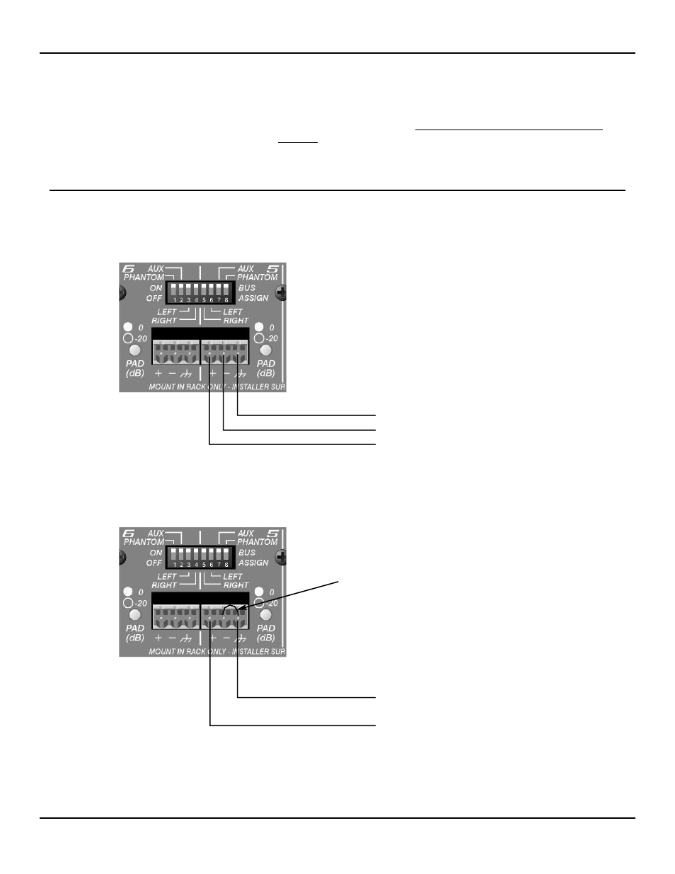
Audio Input
The inputs to the SMR 821 are balanced. This means that there are three wires for each connection, a positive, negative and
shield. These should be connected to each pin accordingly.
Shield
Audio Negative
Audio Positive
Balanced Microphone or Line Level Input
Figure 1. Balanced Audio Input Connections
Shield
Insert jumper wire between the negative
and shield pins for un-balanced circuits.
Audio “Hot” or Positive
Un-Balanced Microphone or Line Level Input
Figure 2. Un-Balanced Audio Input Connections