Fig. 4 – Poulan 964 04 06-07 User Manual
Page 8
8
02360
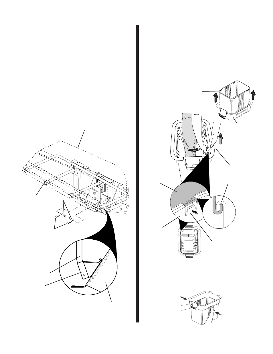
MOUNTING TO TRACTOR (See Fig. 4)
Use Hardware - - GROUP "C"
NOTE: For ease of assembly, you may wish to obtain the
as sis tance of another person for mounting assembly to
tractor.
1. Raise seat on tractor to allow assembly to be mount-
ed.
2. With cover closed, lift assembly and place support
posts into mount ing bracket. Allow assembly to rest
on bottom of mounting bracket.
3. Line up holes in mounting bracket with holes in support
posts and insert support post clevis pins. Secure with
re tain er springs.
4. Install the four (4) tubing end caps onto container sup-
port. Tap each end cap onto container support tubes
to seat securely.
4
COVER AS SEM BLY
Fig. 4
END CAP
SUPPORT
POST
MOUNTING
BRACKET
SUPPORT
POST
CLEVIS
PINS
RE TAIN ER
SPRINGS
DRAWBAR
CONTAINER ASSEMBLY (See Fig. 5)
No hardware required
1. Place bottom half inside of top half, as shown.
2. Place one foot inside bottom half and lift top half to
meet bottom half.
3. Press halves tightly together while lifting top to lock
into place as shown.
IMPORTANT: BEFORE LOCKING THE TABS, HOOKED EDGES
ON BOTH HALVES MUST OVERLAP TO FORM SEAL AS SHOWN
IN INSET.
4. Repeat for other containers.
PRESS TOGETHER
TO FORM SEAL
WHILE LIFTING
TOP HALF
02089
CONTAINER
BOTTOM
HALF
CONTAINER
TOP HALF
ASSEMBLY CHECK: Squeeze sides of lower half of con-
tain er and check that there is no gap between upper and
lower halves. If a gap appears, unlock tabs to separate
container halves and repeat instructions above.
LOCKING
TAB
WA
RNI
NG
Do
no
t o
pe
rat
e m
ow
er
un
les
s c
ont
ain
er
is
prop
e
rly
iss
ub
jec
t to
we
ar
an
d d
eti
eri
ora
tio
n.
Che
ck
ba
g f
req
u
en
tly.
Re
pla
ce
wh
en
crac
ke
d o
r d
am
ag
ed
. U
se
onl
y a
rec
om
me
nd
ed
rep
lac
eme
nt
con
tai
ner
.
02097
FIG. 5
5
027
39
CONTAINER
BOTTOM HALF
CONTAINER
TOP HALF