Pinning – Philips TDA1563Q User Manual
Page 4
2000 Feb 09
4
Philips Semiconductors
Product specification
2
×
25 W high efficiency car radio power
amplifier
TDA1563Q
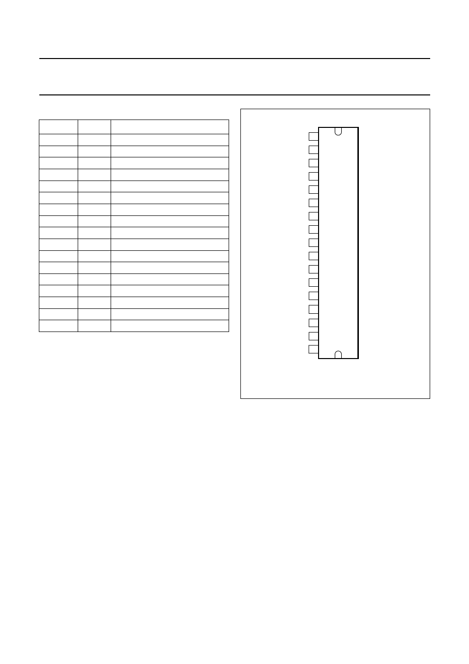
PINNING
SYMBOL
PIN
DESCRIPTION
IN1+
1
non-inverting input 1
IN1
−
2
inverting input 1
CIN
3
common input
CSE
4
electrolytic capacitor for SE mode
V
P1
5
supply voltage 1
MODE
6
mute/standby/operating
OUT1
−
7
inverting output 1
OUT1+
8
non-inverting output 1
GND
9
ground
OUT2
−
10
inverting output 2
OUT2+
11
non-inverting output 2
SC
12
selectable clip
V
P2
13
supply voltage 2
DIAG
14
diagnostic: protection/temperature
CLIP
15
diagnostic: clip detection
IN2
−
16
inverting input 2
IN2+
17
non-inverting input 2
handbook, halfpage
TDA1563Q
MGR174
IN1
+
IN1
−
CIN
CSE
VP1
MODE
OUT1
−
OUT1
+
GND
OUT2
−
OUT2
+
SC
VP2
DIAG
CLIP
IN2
−
IN2
+
1
2
3
4
5
6
7
8
9
10
11
12
13
14
15
16
17
Fig.2 Pin configuration.