3 computer control functions, 1 serial control (see chapters 3, 4, 5 and 6), 2 extend terminal control (see chapter 9) – Pioneer V8000 User Manual
Page 10: 3 external power control
Computer Control
- 3
Refer to the instruction manual about ‘STOP ST’.
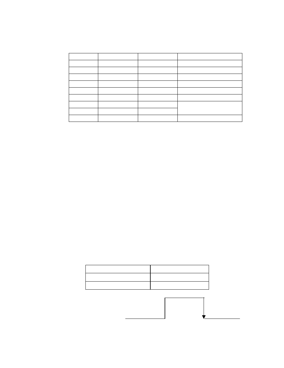
9-pin D-Sub connector
Pin #
Terminal
Input/Output
Function
1 NC
2 RxD Input
receive
data
3 TxD Output
send
data
4
DTR
Output
data terminal ready
5 GND
--
ground
6 NC
7 RTS Output
8 CTS Input
CTS is returned to RTS as
it is.
9 NC
2.3
Computer Control Functions
2.3.1 Serial Control (see Chapters 3, 4, 5 and 6)
The player and computer are based upon the RS-232C protocol and
are connected through the TxD, RxD, DTR and GND terminals.
2.3.2 Extend Terminal Control (see Chapter 9)
Control the player with the Extend Terminal Switches (SW#).
Even if the Key Lock is set (active), the extend terminal control is
available.
2.3.3 External Power Control
Control the player’s power with the Power Pin within the Interface
Connector.
If the player detects a high signal throughput (100m/sec or more)
during the Standby mode, the player powers ON. If the player
detects the same signal during the Power ON mode, the player
powers OFF and switches to the Standby mode.
The specifications for the Power pin are as follows:
Maximum Input Voltage
Less Than 12V
High Level Signal
More Than 3.3V
Low Level Signal
Less Than 0.5V
Standby mode
more than
100 msec
Power ON