Patton electronic 2450 User Manual
Page 5
Switch S1-6: Front Panel Switch Enable/Disable
Switch S1-6 determines whether the front panel switches may be
used to perform diagnostic functions.
S1-6
Activation
Description
Off
Enabled
Front panel switches may be used
to activate/terminate diagnostics
On
Disabled
Front panel switches will have no
effect on operation of the unit
Switch S1-7: DTE Loop Request Line Enable/Disable
The setting for switch S1-7 determines whether the DTE signals
can be used to activate/terminate the loopback diagnostic modes and
BER test patterns.
DTE TM Line
S1-7
Activation
Description
Off
Enabled
DTE Loop request line switches
may be used to activate/terminate
diagnostics.
On
Disabled
DTE loop request lines will
have no effect on operation of
the unit.
Switch S1-8: Receive RDL Enable/Disable
Switch S1-8 determines whether or not the unit will respond to loop
requests from the remote device.
S1-6
Activation
Description
Off
Enabled
Unit wil respond to loop requests
from the remote device.
On
Disabled
Unit wil ignore loop requests from
the remote device.
4.0 INSTALLATION
The Model 2450 is designed for 4-wire, full duplex communication
over a DDS or Clear Channel carrier circuit, or over dedicated twisted
pair. This section will describe proper connection of the line interface,
the DTE (terminal) interface, and the AC power supply.
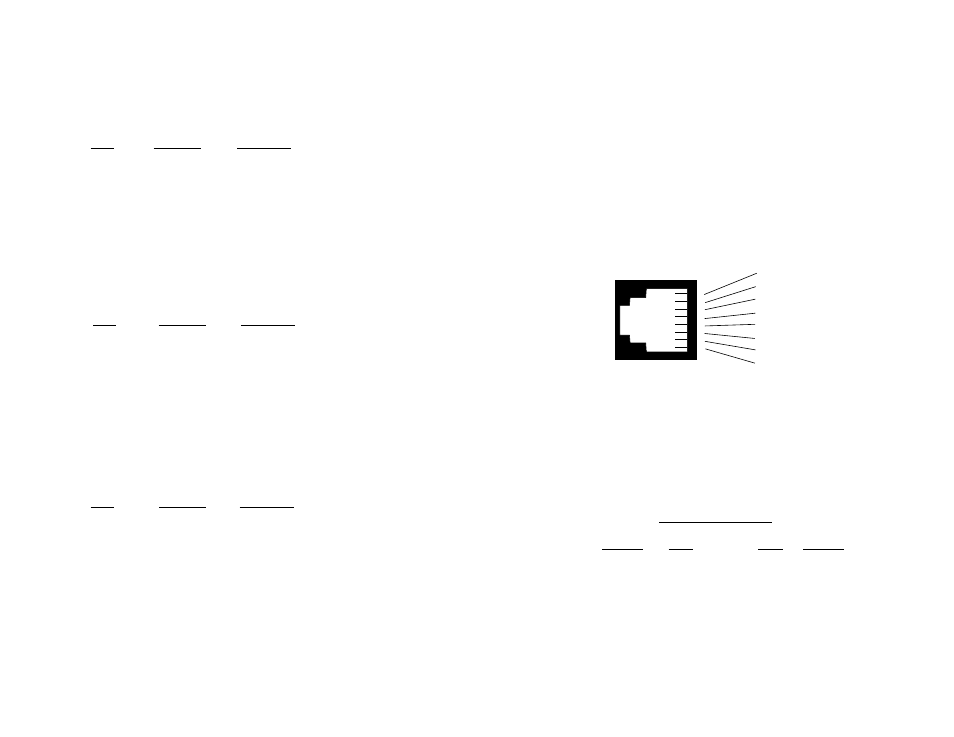
4.1 LINE (NETWORK) CONNECTION
The RJ-48S port on a Model 2450 CSU/DSU is prewired for a
standard TELCO wiring environment (see Figure 4, below). Connect
this port to the RJ-48S jack provided by your digital service carrier
using a
straight through
twisted pair cable between 19 and 26 AWG.
To be sure you have the right wiring, use the table below as a guide.
4.1.1 CONNECTING OVER PRIVATE TWISTED PAIR
If you are using a pair of Model 2450s as short range modems over
private twisted pair, make the connection between them using a twisted
pair
crossover cable
pinned according to the diagram below.
RJ-48S Cable (4-Wire)
SIGNAL
PIN#
PIN#
SIGNAL
TX+
1-----------------------7
RX+
TX-
2-----------------------8
RX-
RX+
7-----------------------1
TX+
RX-
8-----------------------2
TX-
8
7
Figure 4. Interface pinouts for Model 2450 RJ-48S jack.
1 (TX+)
2 (TX-)
3 (N/C)
4 (N/C)
5 (N/C)
6 (N/C)
7 (RX+)
8 (RX-)
1
2
3
4
5
6
7
8