0 illustrated wiring diagram, Control pcb – Baxi Potterton PERFORMA 30 HE User Manual
Page 47
15.0
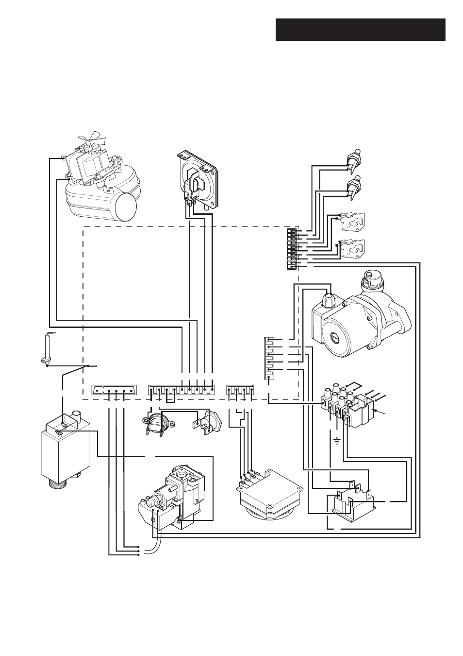
Illustrated Wiring Diagram
47
© Baxi Heating UK Ltd 2007
- brown
- black
- blue
- red
br
bk
b
r
- green
- green / yellow
- white
g
g/y
w
Optional Timers
Domestic Hot Water
Temperature Sensor
Reset Selector Switch
Control PCB
A1
A2
A3
A4
A5
F2
1
bk
bk
r
r
g
g
g
r
g
r
2
1
2
3
3
4
1
1
2
3
4
5
6
10
9
8
7
6
5
4
3
2
1
2
3
4
4
5
5
6
7
8
9
Central Heating
Temperature Sensor
Fan
Gas Valve
Overheat Stat
Hydraulic Differential
Pressure Switch
Domestic Hot Water Flow
Priority Pressure Switch
Air Pressure
Switch
Flame
Mains Input
Fuse
Link
g/y
g/y
b
br
bk
br
b
bk
Sensing
Electrode
Pump
b
b
b
bk
b
b
b
br
br
b
b
r
bk
bk
br
bk
br
br
br
Flue Stat
1
2
3
4
Condensate
Trap
g/y
g/y