Warning – Poulan 545117551 User Manual
Page 12
12
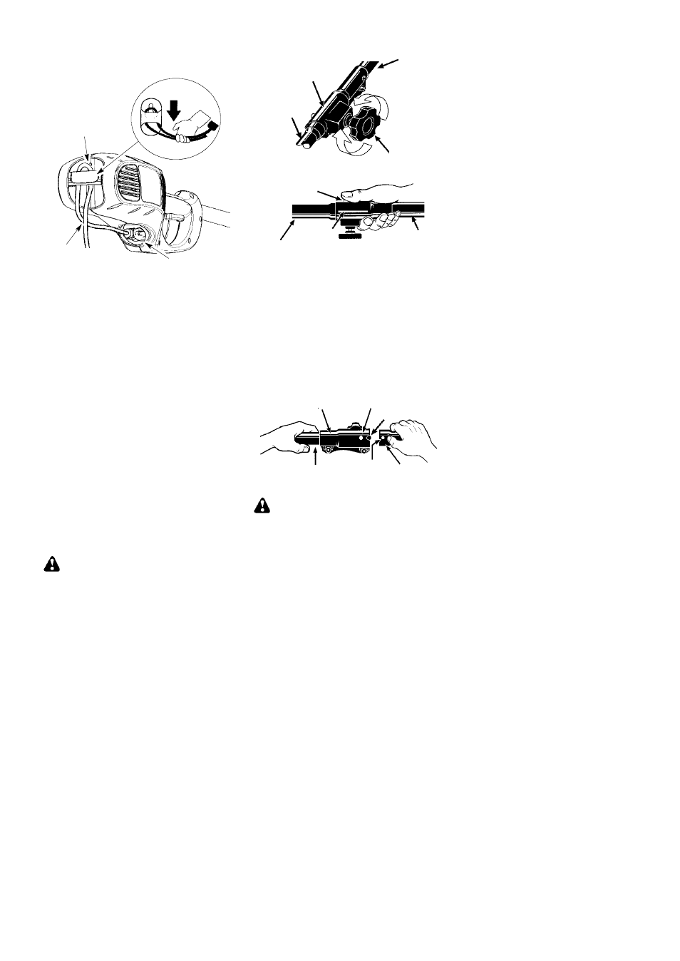
ATTACH THE EXTENSION
CORD TO YOUR UNIT
Make a loop in your extension cord and attach
the cord as shown. Ensure the plug and cord
are firmly and fully engaged.
Cord Retainer
Extension Cord
Recessed Plug on Unit
BEFORE STARTING UNIT
Be sure to read the electrical safety information
in the safety rules section of this manual before
you begin. If you do not understand the electrical
safety information do not attempt to use your
unit. Seek help from someone that does under-
stand the information or call the customer assis-
tance help line at 1-800-554-6723.
GUIDE BAR AND CHAIN OIL
The bar and chain require lubrication. The chain
oiler provides continuous lubrication to the chain
and guide bar. Lack of oil will quickly ruin the bar
and chain. Too little oil will cause overheating
shown by smoke coming from the chain and/or
discoloration of the bar. The oil output is auto-
matically metered during operation. Always fill
the bar oil tank before and during use as needed
(capacity = 4.6 fl. oz.).
Genuine Poulan bar and chain oil is recom-
mended to protect your unit against exces-
sive wear from heat and friction. Poulan oil
resists high temperature thinning.
If Poulan bar and chain oil is not available,
use a good grade SAE 30 oil.
S
Never use waste oil for bar and chain lubri-
cation.
S
Always stop the unit before removing the oil
cap.
WARNING:
Always stop unit and dis-
connect from power source before removing
or installing attachments.
REMOVING PRUNER ATTACHMENT,
LINE TRIMMER ATTACHMENT OR
OTHER OPTIONAL ATTACHMENTS
CAUTION:
When removing or installing at-
tachments, place the unit on a flat surface for
stability.
1. Loosen the coupler by turning the knob
counterclockwise.
Coupler
Knob
LOOSEN
TIGHTEN
Upper Shaft
Lower
Attachment
2. Press and hold the locking/release button.
Locking/Release
Button
Coupler
Upper Shaft
Lower Attachment
3. While securely holding the motor housing
and upper shaft, pull the attachment
straight out of the coupler.
INSTALLING OPTIONAL ATTACH-
MENTS
1. Remove the shaft cap from the attach-
ment (if present).
2. Position locking/release button of attach-
ment into guide recess of coupler.
3. Push the attachment into the coupler until
the locking/release button snaps into the
primary hole.
4. Before using the unit, tighten the knob se-
curely by turning clockwise.
Coupler Primary Hole
Upper
Shaft
Locking/
Release
Button
Attachment
Guide Recess
WARNING:
Make sure the locking/
release button is locked in the primary hole
and the knob is securely tightened before op-
erating the unit.
INSTALLING ATTACHMENT
HANGER
An attachment hanger is provided for storage
when attachment is not in use.
To install hanger on attachment:
1. Remove the shaft cap from the attach-
ment (if present) and discard.
2. Press and hold the locking/release button.
3. Push hanger onto the attachment until the
locking/release button snaps into the
hole.