Diagrams, V160-s – Lincoln Electric INVERTEC V160-S User Manual
Page 24
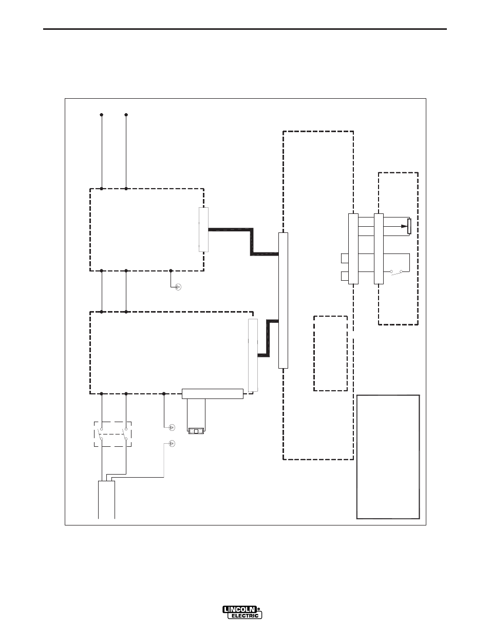
F-1
DIAGRAMS
F-1
V160-S
NOTE: This diagram is for r
efer
ence only
. It may not be accurate for all machines cover
ed by this manual. The specific diag
ram for a particular code is pasted inside
the machine on one of the enclosur
e panels. If the diagram is illegible, write to the Service Department for a r
eplacement. G
ive the equipment code number
.
V160-S WIRING DIAGRAM
1
2
4
3
AC1
AC2
GND
S1
BLUE
BROWN
WHITE
BLACK
GREEN
GREEN /YELLOW
OR
115/230/1/50/60
Vac
FAN
JP2
DC-A
DC+
Y/G
BLACK
RED
DC+
DC-
GND
12
36
5
41
0
11
9
8
7
12
15
13
14
16
13
5
4
21
0
67
9
8
JP1
JP1
1
3
54
2
10
6
7
98
11
13
12
J1
14
15
16
17
24
2
3
22
21
20
19
18
26
2
5
DISPLAY BOARD
W05X0245
(SCHEMATIC: X0245)
WELD CONTROLLER
W05X0233
(SCHEMATIC: X0233)
W1
W2
-
+
24
7
68
REMOTE
CONNECTOR
DE
C
B
A
13
5
JP1
INPUT BOARD
W05X0250
(SCHEMATIC: X0203)
INVERTER BOARD
W05X0190
(SCHEMATIC: X0190)
1
3
4
2
X0261
WARNING: HIGH VOLTAGE CAN KILL
* Do not operate with covers removed.
* Disconnect input power by unplugging
power cord before servicing.
* Do not touch electrically live parts.
* Only qualified persons should install, use or service this machine.
CW
WIRING DIAGRAM CODE 10877