Figure 3- connect the ac adapter, Figure 4- connect each cpu, 5 v d c 2 a – Lightwave Communications USB-Wizard User Manual
Page 9: 5 v d c, Rear view of usb-wizard rear view of usb wizard
5
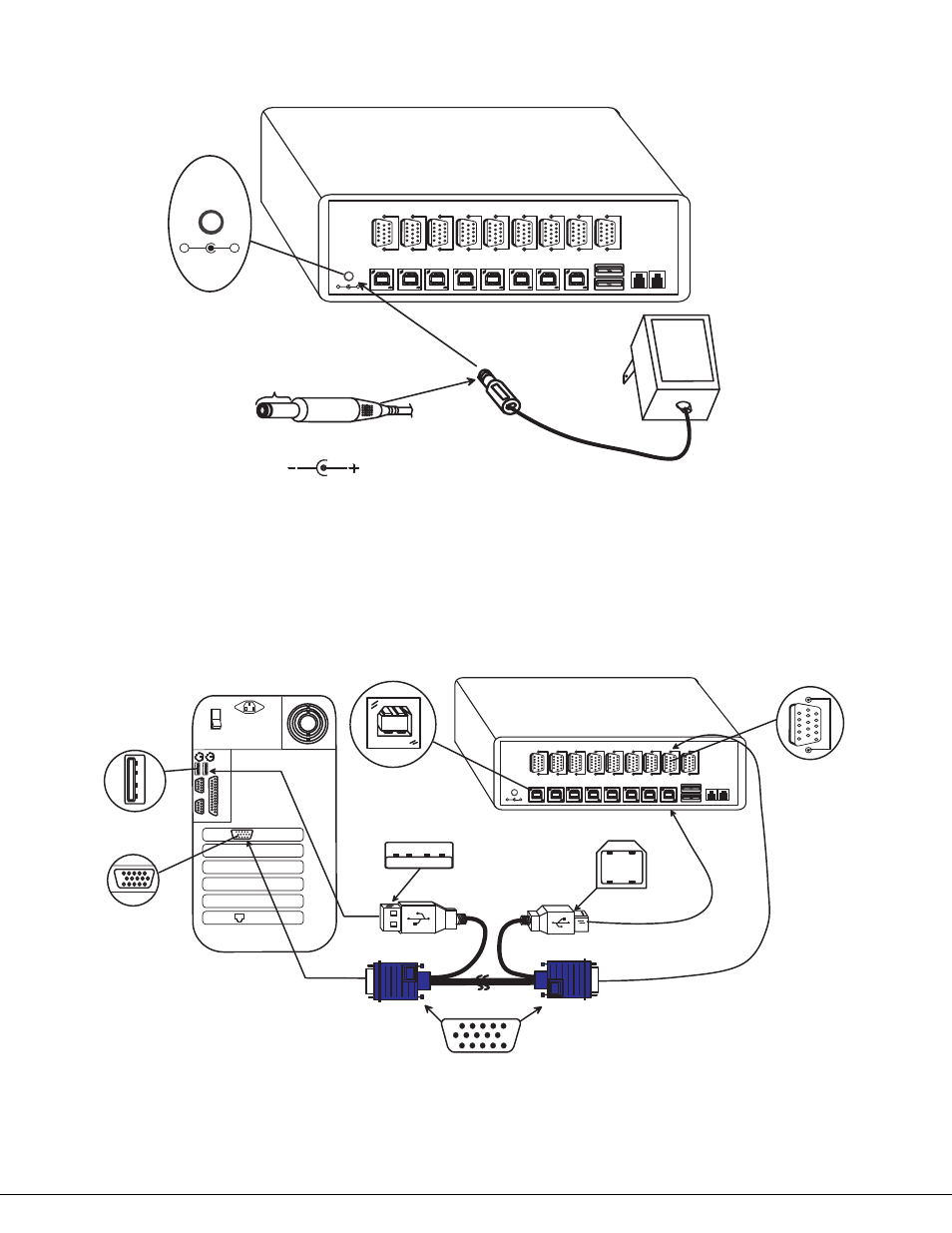
5. When cascading switches, configure dip-switches accordingly (see Tables 1 & 2 on page 8).
6. Power-up the
USB Wizard. (See Fig. 3 below.)
Figure 3- Connect the AC adapter
Note: Do not press any port buttons until the PORT 1 LED on the front panel of the switch illuminates.
7. Connect each CPU to the USB
Wizard using a USBVEXT-xx-MM video and input device interface cable – REQUIRED
(not supplied). (See Fig. 4 below.)
8. Group the input device and monitor interface cables from each CPU, making sure that cables from the first CPU are
connected to the
USB Wizard switch at connectors CPU 1 and VIDEO 1. Cables from the second CPU should
connect to CPU 2 and VIDEO 2 connectors...etc.
Figure 4- Connect each CPU
1 5 H D M a l e
V i d e o C o n n e c t o r
C P U 8
D E V I C E S
C P U 7
C P U 6
C P U 5
C P U 4
C P U 3
C P U 2
C P U 1
5 V D C
2 A
-
+
V
I
D
E
O
8
R
V
I
D
E
O
7
V
I
D
E
O
6
V
I
D
E
O
5
V
I
D
E
O
4
V
I
D
E
O
3
V
I
D
E
O
2
V
I
D
E
O
1
M
O
N
I
T
O
R
D A I S Y
O U T
D A I S Y
I N
U S B T y p e B
F f e m a l e
U S B T y p e A F e m a l e
U S B T y p e A M a l e
U S B V E X T - x x - M M
1 5 H D F e m a l e
V i d e o C o n n e c t o r
V
I
D
E
O
1
U S B T y p e B
M a l e
1 5 H D F e m a l e
V i d e o C o n n e c t o r
R e a r V i e w o f W i n d o w s U S B C P U
V i d e o P o r t
I n p u t D e v i c e P o r t
C P U 8
D E V I C E S
C P U 7
C P U 6
C P U 5
C P U 4
C P U 3
C P U 2
C P U 1
5 V D C
2 A
-
+
V
I
D
E
O
8
R
V
I
D
E
O
7
V
I
D
E
O
6
V
I
D
E
O
5
V
I
D
E
O
4
V
I
D
E
O
3
V
I
D
E
O
2
V
I
D
E
O
1
M
O
N
I
T
O
R
D A I S Y
O U T
D A I S Y
I N
5 V D C
A d a p t e r
A C
A D A P T E R
B a r r e l
( I n s i d e
b a r r e l )
( O u t s i d e
b a r r e l )
P o w e r C o n n e c t o r
2 . 1 m m x 5 . 5 m m F e m a l e
5 V D C @ 2 . 5 A O U T P U T
5 V D C
2 A
-
+
Rear View of USB-Wizard
Rear View of USB Wizard