Lochinvar Commercial Electric Water Heaters User Manual
Page 7
7
JACKET ASSEMBLY
Outer Jacket - The outer jacket assembly is constructed
from heavy gauge steel. The exterior surface is specially
prepared and phosphate coated to allow application of a
multiple coat enamel paint process. This coating process
insures a long life from the jacket assembly.
STANDARD EQUIPMENT
Your commercial electric water heater is equipped with the
following as standard equipment.
• Low watt density immersion heating elements with a
copper sheath and a tin plate.
• Internal fusing of all element power circuits is provided
when current draw is in excess of 48 amps
• Fused power circuits provided in increments of a
maximum 48 amps for additional safety.
• Fuse cartridges are rated at 1,000,000 amps interrupting
capacity.
• A fully painted heavy gauge steel outer jacket and
electrical control panel are provided.
• Electrical control panel is provided with a hinged door.
• A glass lined steel tank constructed to standard
specifications and provided with a magnesium anode.
• ASME rated temperature and pressure relief valve
provided by factory to insure safe heater operation.
• Terminal block connections are installed by the factory for
safe easy wiring connection.
• Manual reset high water temperature limit control.
• Surface mount thermostats (one per each immersion
heating element).
• 180°F temperature operation is possible to provide water
for sanitizing applications.
• Insulated to meet latest edition of ASHRAE 90.1 energy
efficiency standards.
• 3 year limited warranty provides protection against failure
of tanks due to defects in material and workmanship in
commercial application.
• Underwriter's Laboratories, Inc. listing for all models as a
commercial electric water heater.
The following items are available as extra cost options.
• Immersion thermostats with magnetic contactors
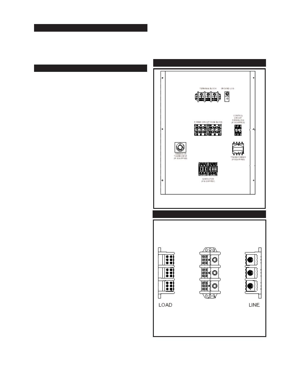
FIG.
5
Electrical Control Panel Component
Location Drawing
COMPONENTS AND CONTROLS
TERMINAL BLOCK
FIG. 6 Main Power Terminal Block