Wiring diagram, Service manual 21 schematic diagram – LG HB8004R User Manual
Page 21
Service Manual 21
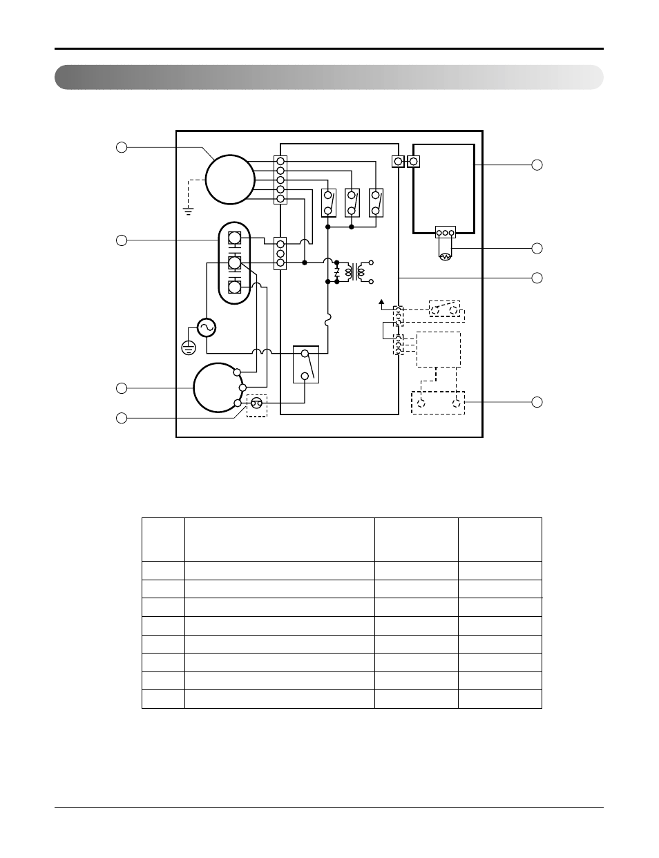
Schematic Diagram
Wiring Diagram
MOTOR ASSY
CAPACITOR
COMPRESSOR
OVERLOAD PROTECTOR
DC PCB ASSEMBLY
AC PCB ASSEMBLY
THERMISTOR
PLASMA FILTER ASSY
1
2
3
4
5
6
7
8
1
1
1
1
1
1
1
1
S
S
S
S
S
S
S
S
LOCATION
NO.
DESCRIPTION
REMARKS
Q'TY
PER SET
MOTOR
COMP.
CAPACITOR
DC PCB
ASSEMBLY
THERMISTOR
AIR FILTER
ASSEMBLY
AC PCB
ASSEMBLY
WIRING DIAGRAM
SWITCH
H.V.
ASSEMBLY
BK
CN-MOTOR
CN-PWR
DC12V
ZNR01J
CN-12V
CN-HVB
RY-COMP
3
4
FUSE
250V/T3.15A
RY
-L
O
W
RY
-MED
RY
-HI
CN-AC/DC
POWER
TRANS
CN-AC/DC
CN-TH1
BL
RD
RD
BK
BL
R
S
C
OLP
YL
OR
YL
F
C
H
WH
(
BL
)
(
Ribbed
)
BK
(
BR
)
(
Plain
)
GN/YL
(
GN
)
GN/YL
(
GN
)
BK
RD
OR
(
BR
)
1
5
7
6
8
4
2
3
S: Service Parts
N: Non Service Parts