Initial set-up, System integration diagram, Finalizing receiver/amplifier connections – LightSpeed Technologies 850IR User Manual
Page 14: Final check, Projector, Dvd/vcr
8 5 0 i R U s e r M a n u a l
850iR User Manual | 10
13 | 850iR User Manual
8 5 0 i R U s e r M a n u a l
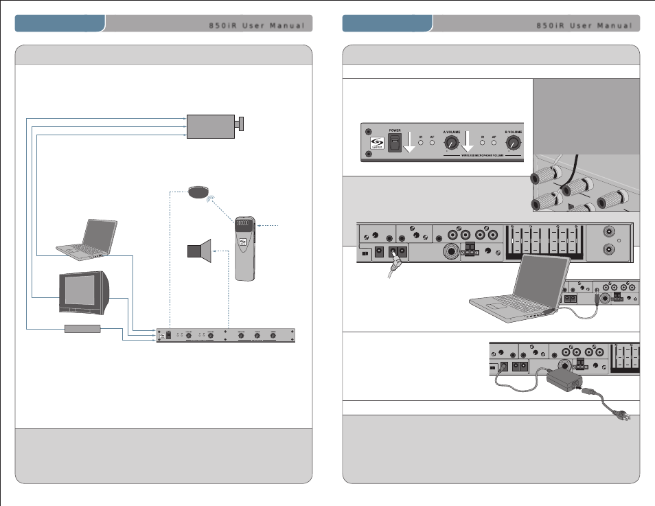
2. Ensure speaker wire
connections are secure
and not frayed. Each
speaker switch located
to the right of the
speaker jack should be
in the “ON” position.
3. Connect the charging cables to yellow charging
jacks labeled “CHARGERS.” The loose end will be
connected to the cradle charger input jack or
directly to microphone.
1. Ensure the power switch is in the “OFF” position
and all front panel volume controls are turned
fully counter-clockwise.
6. Connect DC end of power supply
to the black power jack labeled
“DC POWER.”
7. Connect the black AC power cable
from the power supply to a wall outlet.
SPEAKER OUTPUTS
250 400
700
1K
1K4
2K5
4K
6K
+10
0
-10
OFF
OFF
OFF
OFF
ON
ON
ON
ON
VOL.
ADJ.
ALD OUT AUX OUT
VOL.
ADJ.
COMPUTER
AUDIO INPUTS
TV/VCR
CD/DVD
800iX
INPUT
PAGING INPUT
ADJ
DC POWER CHARGERS
24VDC
L
L
R
R
SENSOR INPUTS
SENSOR
SHORT
1
2
3
4
FINALIZING RECEIVER/AMPLIFIER CONNECTIONS
INITIAL SET-UP
SPEAKER OUTPUTS
250 400
700
1K
1K4
2K5
4K
6K
+10
0
-10
OFF
OFF
OFF
OFF
ON
ON
ON
ON
VOL.
ADJ.
ALD OUT AUX OUT
VOL.
ADJ.
COMPUTER
AUDIO INPUTS
TV/VCR
CD/DVD
800iX
INPUT
PAGING INPUT
ADJ
DC POWER CHARGERS
24VDC
L
L
R
R
SENSOR INPUTS
SENSOR
SHORT
1
2
3
4
SPEAKER OUTPUTS
250 400
700
1K
1K4
2K5
4K
6K
+10
0
-10
OFF
OFF
OFF
OFF
ON
ON
ON
ON
VOL.
ADJ.
ALD OUT AUX OUT
VOL.
ADJ.
COMPUTER
AUDIO INPUTS
TV/VCR
CD/DVD
800iX
INPUT
PAGING INPUT
ADJ
DC POWER CHARGERS
24VDC
L
L
R
R
SENSOR INPUTS
SENSOR
SHORT
1
2
3
4
LES 850iR Classroom Amplification System
4. Connect any auxiliary audio
sources to corresponding
labeled input.
5. Ensure sensor cable is attached
securely.
>>
>>
>>
>>
1. Ensure all cables are appropriately routed out of walking paths and work areas to
prevent safety hazards to individuals in the room.
2. The amplifier packing material should be kept for warranty shipping purposes.
Dispose of remaining system-packing material in the appropriate refuse containers.
Leave microphones charging so they are ready for use. Microphones will need to be
charged on a daily basis.
FINAL CHECK
LightSPEED amplifier controls the volume of each source
individually (one volume control for each source).
SYSTEM INTEGRATION DIAGRAM
Projector
DVD/VCR
Speaker(s)
IR Sensor
Teacher’s
Microphone
Projector
Audio In
Audio Out
IR Transmission
Video In
LES 850iR Classroom Amplification System
LT-71
Audio Out
Audio Out
Video Out
Video Out
VGA Out
850iR
1
2
>>