Product overview, 152 mm – Linksys WAG54G2 User Manual
Page 5
Chapter 1
Product Overview
2
Wireless ADSL2+ Gateway
Follow these instructions:
Determine where you want to mount the device. Make
1.
sure that the wall you use is smooth, flat, dry, and
sturdy. Also make sure the location is within reach of
an electrical outlet.
Drill two holes into the wall. Make sure the holes are
2.
152 mm (6 inches) apart.
Insert a screw into each hole and leave 3 mm
3.
(0.12 inches) of its head exposed.
Maneuver the device so the wall-mount slots line up
4.
with the two screws.
Place the wall-mount slots over the screws and slide
5.
the device down until the screws fit snugly into the
wall-mount slots.
Wall-Mounting Placement
(WAG54G2, WAG110, WAG160N Only)
The device has two wall-mount slots on its bottom
panel. The distance between the slots is 152 mm
(6 inches).
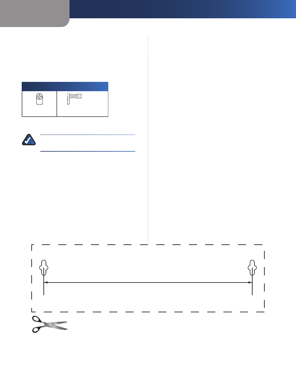
Two screws are needed to mount the device.
Suggested Mounting Hardware
2.5-3.0 mm
4-5 mm
1-1.5 mm
Note: Mounting hardware illustrations are not
†
true to scale.
NOTE:
Linksys is not responsible for damages
incurred by insecure wall-mounting hardware.
152 mm
Wall Mounting Template