Life Fitness 4000 User Manual
Page 7
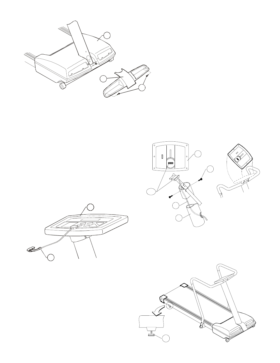
Step 8
Press the VENT COVER (14) into position on the
MOTOR COVER (A). Install the two SCREWS
(#19) into the corresponding holes on the sides of
the VENT COVER and the notch of the MOTOR
COVER and secure in place.
Step 9
Plug the 12-PIN CONNECTOR (12P) of the WIRE HARNESS (B) protruding from the top of the MONOCOLUMN
(#1) into the corresponding PC BOARD CONNECTOR located on the back of the DISPLAY CONSOLE (#16). Once
connected, feed the excess cable carefully back into the top of the MONOCOLUMN and lower the DISPLAY
CONSOLE into position on the MONOCOLUMN. Secure the DISPLAY CONSOLE to the MONOCOLUMN with the
two SCREWS (#17).
Step 10
Place the magnet side of the STOP KEY (#11) in the
space provided on the face of the DISPLAY CONSOLE
(#16). Check to ensure that the ON/OFF switch, located
next to the POWER CORD point of entry, is in the OFF
[O] position. Plug the treadmill POWER CORD into a
properly grounded outlet and change the switch setting to
the ON [I] position.
Step 11
The treadmill STRIDING BELT is properly centered at the
factory. However, the LEVELING LEGS (F) may need to be
adjusted once the unit is placed in its intended location.
Step 12
Check to insure that the STRIDING BELT is
centered and tensioned properly according to the
instructions in the Operation Manual before running.
Failure to do so could cause damage to the
STRIDING BELT.
12P
16
17
B
1
F
G
13
C
11
16