Life Fitness 4000 User Manual
Page 6
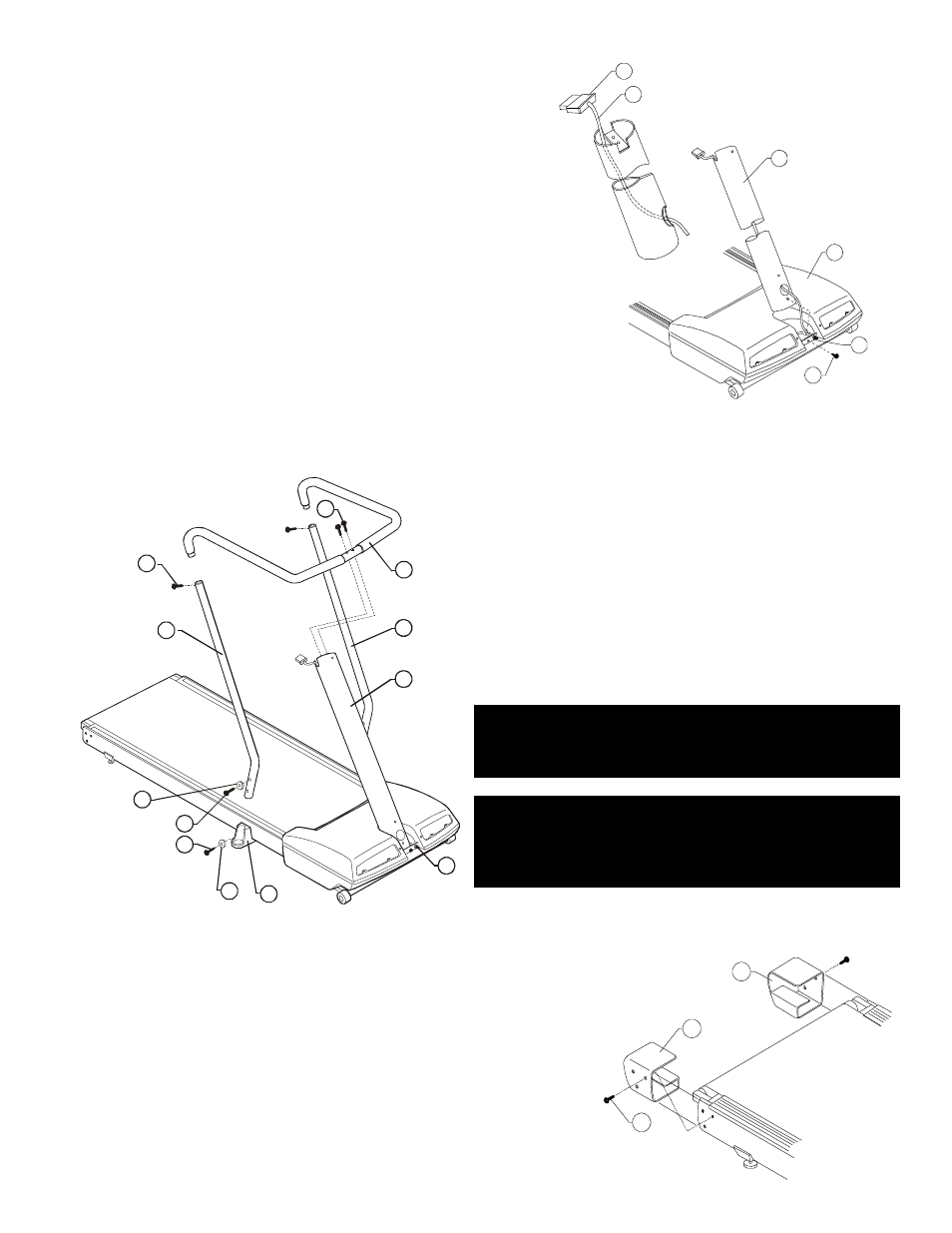
Step 1
Snap the VENT COVER off the MOTOR COVER (A) by pulling
outward. Carefully untie and uncoil the WIRE HARNESS (B)
tucked into the front center cutout of the MOTOR COVER. Pull
gently on the WIRE HARNESS to remove any slack.
Step 2
Lay the MONOCOLUMN (#1) on the STRIDING BELT and feed
the WIRE HARNESS CONNECTOR (C) into the access hole
provided near the bottom front side of the MONOCOLUMN. The
WIRE HARNESS should exit through the top on the user side
(toward the STRIDING BELT) of the metal bar welded across the
top center of the MONOCOLUMN.
Step 3
Slide the MONOCOLUMN (#1) into position through the U-
BRACKET (D) in the center of the MOTOR COVER (A). The large
access hole on the front side of the MONOCOLUMN should be
placed down and toward the front of the machine when properly
installed. Secure the MONOCOLUMN in position by lightly
tightening the nuts on the U-BRACKET. Insert the Phillips SCREW (#2) through the frame and into the bottom
hole of the MONOCOLUMN. Tighten the SCREW until finger-tight only.
Step 4
Insert the ends of the VERTICAL HANDRAILS (#6) into
the matching ends of the foam padded HANDLEBAR (#3).
Align the screw holes and secure each vertical post in
place with a loosely installed SCREW (#4). Slide each foot
of the completed HANDLEBAR/HANDRAIL ASSEMBLY
into the MOUNTING BRACKETS (E) located on either
side of the treadmill. Install the two 2” SCREWS (#7) and
WASHERS/COVERS (#12) and the two 2 1/2” SCREWS
(#8) and WASHERS/COVERS (#12) until finger-tight only
to hold the HANDLEBAR/HANDRAIL ASSEMBLY in
position with the MONOCOLUMN (#1).
NOTE: THE WASHER / COVERS (#12) ARE CURVED TO
MATCH THE VERTICAL HANDRAILS (#6). BE SURE TO
ALIGN THE WASHER / COVERS PROPERLY BEFORE
TIGHTENING THE SCREWS (#7 & #8).
NOTE: LA RONDELLE / COUVERTURES (# 12) SONT
COURBÉES POUR APPARIER LES BALUSTRADES
VERTICALES (# 6). SOYEZ SÛR D'ALIGNER LA
RONDELLE / COUVERTURES CORRECTEMENT AVANT
DE SERRER LES VIS (#7 & #8).
Step 5
Secure the HANDLEBAR (#3) tightly to top of the MONOCOLUMN (#1)
with two hex key SCREWS (#5).
Step 6
Tighten the U-BRACKET (D) nuts and all previously installed SCREWS
to secure all installations to this point.
Step 7
Position the LEFT and RIGHT ENDCAPS (#9 & #10) and secure them
with three each of the six SCREWS (#15) provided.
C
B
1
A
D
2
10
15
9
4
3
6
6
7
12
8
D
1
5
E
12