Electrical installation, Motor – Linak LA36 User Manual
Page 12
12
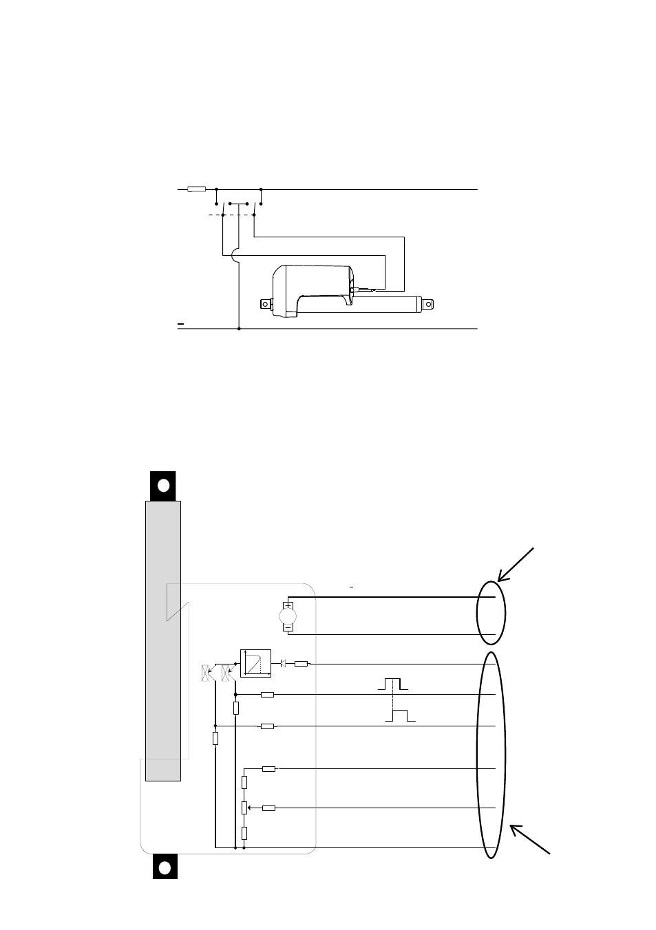
Connection diagrams:
Connections diagram: For 36xxxxx0H/Pxxxxxx and 36xxxxx1H/Pxxxxxx
5 K 6
5 K 6
1 0
1 K
1 0 K
0
0
A
B
B r o w n
B l u e
R e d
Y e l l o w
G r e e n
W h i t e
V i o l e t
B l a c k
M o t o r P o w e r + / - ( o u t / i n ) 1 2 V / 2 4 V / 3 6 V
S u p p l y + 1 2 v t o 3 6 V
H a l l A ( E n d I N )
H a l l B ( E n d O U T )
+ 1 0 V e x i t a t i o n
0 - 1 0 V O u t
G N D
P C B : 0 0 L A 3 6 M H P - X - X
+
-
24
V
8 0 m A
S i g n a l s O U T
1 0
1 0
1 0
Electrical installation
Be aware of BUS actuator - please see the separate installation guide.
Motor connection
Wiring: The actuator direction (forward, reverse) is controlled with a doublethrow
switch with the centre postion “off”.
Motor
+
Actuation
To extend the actuator, connect brown to positive and blue to negative.
To retract the actuator, connect blue to positive and brown to negative.
Power cable
Signal cable