Configuration for modem control, Demo board layout, Figure 2-2. xport demo board layout – Lantronix XPORT 900-563 User Manual
Page 9
2: Demonstration Kit
Configuration for Modem Control
By default, on this demo board, the DCD and DSR signals are not routed to the XPort
module. This makes it necessary to jumper the pins in JP6 in order to route the
signals to the desired CPs on the XPort module.
To be specific, if you wanted to route the serial port DCD signal to CP3 in order to
take advantage of the modem control mode, you would place a jumper wire between
JP6 pin 11 (the DSR signal from the serial port) to JP6 pin 10 (the CP3 pin from the
XPort module).
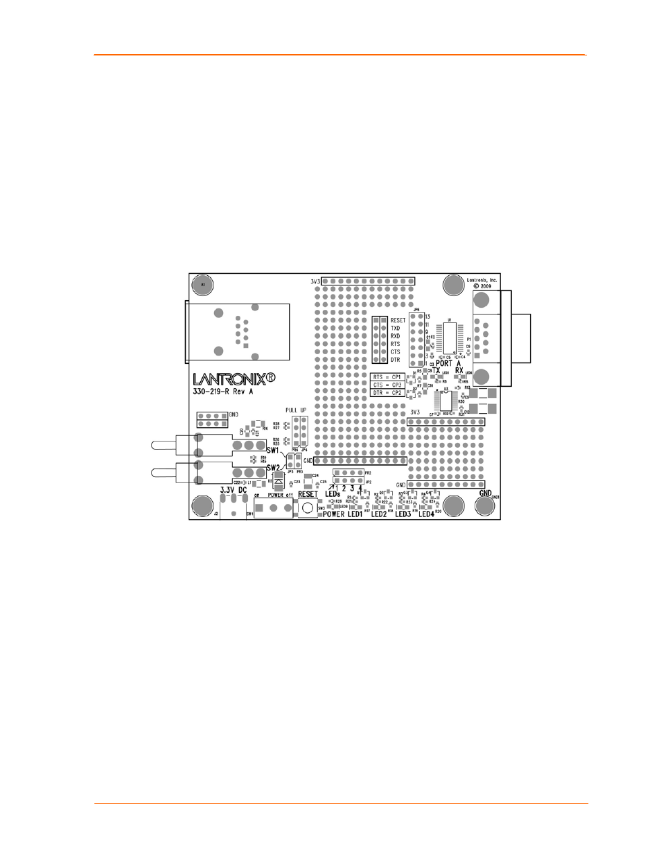
Demo Board Layout
Figure 2-2. XPort Demo Board Layout
XPort Universal Demo Board User Guide
9