Serial interfaces, Demo board block diagram, Figure 2-1. demo board block diagram – Lantronix XPORT 900-563 User Manual
Page 7: Table 2-1. rs-232 signals on serial port 1
2: Demonstration Kit
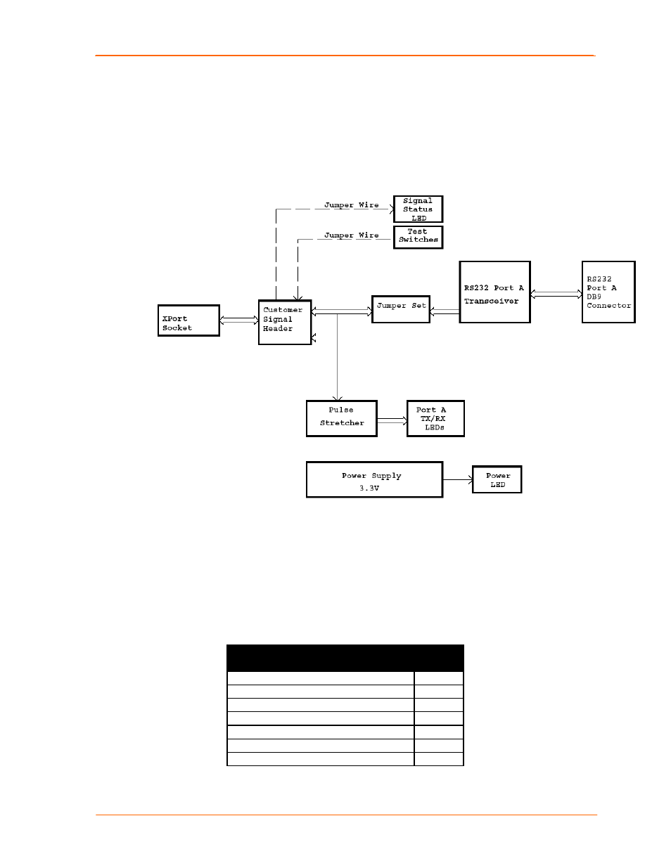
Demo Board Block Diagram
The following drawing is a block diagram of the XPort Demo Board showing the
relationships of the components.
Figure 2-1. Demo Board Block Diagram
Serial Interfaces
The demo board has an RS-232 transceiver for connection to the XPort internal
UART. The table below lists the RS-232 signals and corresponding pins on the demo
board. All signals are level-shifted by the transceivers.
Table 2-1. RS-232 Signals on Serial Port 1
XPort Demo
PIN FUNCTION
DB9
Pin #
Serial Port
CON1
TX_232 (Data Out)
3
RX_232 (Data In)
2
CTS_232 (HW Flow Control Input)
8
RTS_232 (HW Flow Control Output)
7
DTR_232 (Modem Control Output)
4
GND (Ground)
5
XPort Universal Demo Board User Guide
7