System diagrams, A closer look – Lincoln Electric i400 User Manual
Page 6
[6]
Publication E10.11
www.lincolnelectric.com
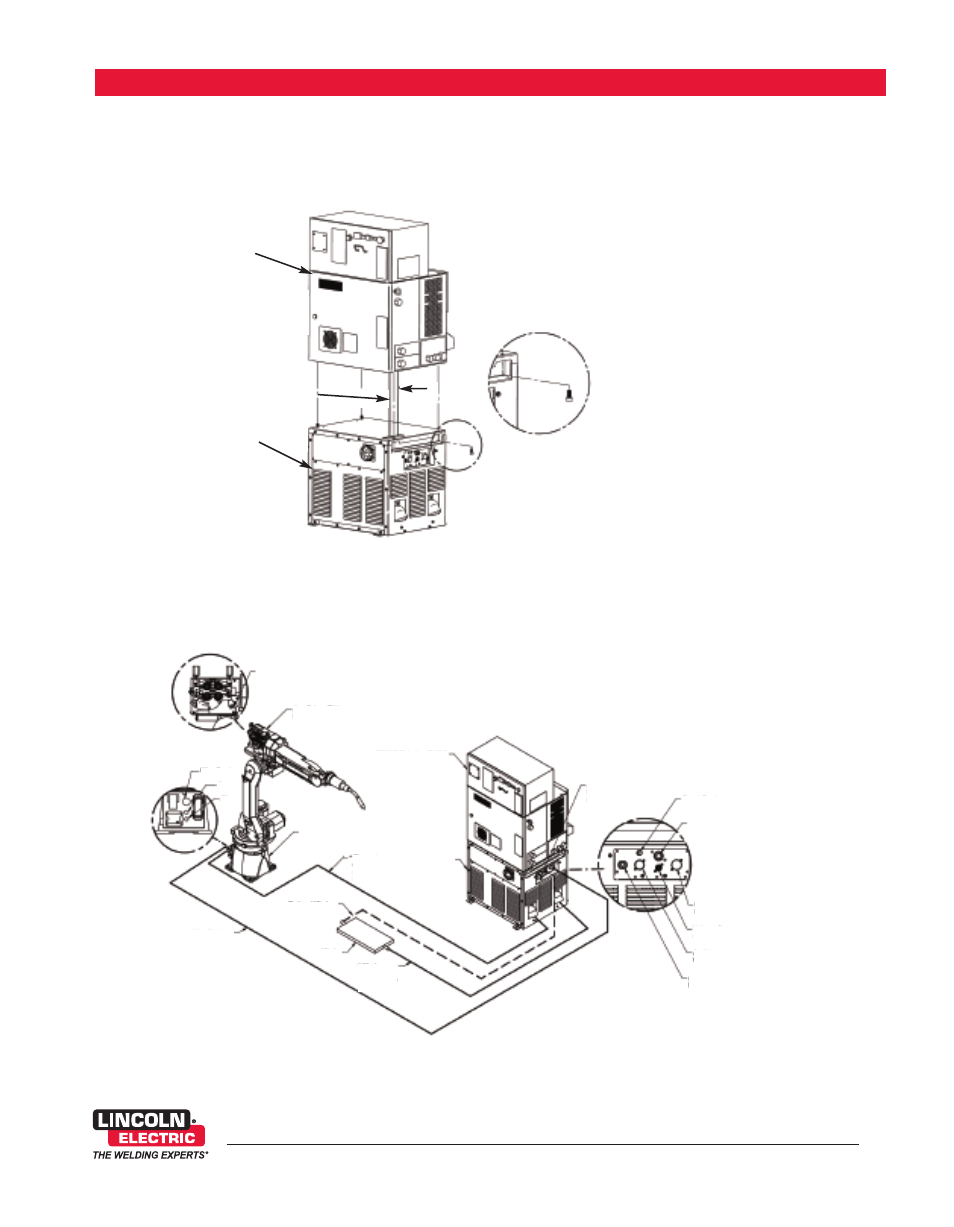
A CLOSER LOOK
SYSTEM DIAGRAMS
Easy connection and installation provides for a stress-free commissioning stage. The ease of use and servicing ensures users
are efficient and productive with their time.
New FANUC
®
Robotics/Lincoln Electric solution providing the latest technology and features together - the best of
robotics and robotic welding combined.
Power Wave
®
i400
K2669-1
FANUC Robotics R-30iA
“a-cabinet” Controller
with Integrated Op Box
*Power
cable
*ArcLink
®
XT
Ethernet
cable
* Refer to Output Cable Guidlines for recommended cable size in Power Wave
®
i400 Instruction Manual.
ArcLink
®
XT
Ethernet Connection
ArcLink
®
Connector
Voltage Sense
Connector
Wire Feeder
Connector
Devicenet
Connector
Circuit Breaker
(15 Amp)
FANUC Robotics R-30iA
“a-cabinet” Controller
with Integrated Op Box
ArcLink
®
XT
Ethernet Cable
(Internal)
Power Wave
®
i400
K2669-1
AutoDrive™ 4R90
K2685-2
Electrode
Connection
ARC Mate™ 1XXiC
Air
Gas
Wire Feeder
Work
Piece
* Electrode
Cable (+)
K2163-xx or
K1842-xx
* Work Cable (+)
K2163-xx or
K1842-xx
Wire Feeder
Control Cable
K1785-xx
Optional Work
Sense Lead (21)
**DETAIL A
A