Maintenance schedule – Lochinvar SYNO 1.5 User Manual
Page 7
User’s Information Manual
2
Maintenance schedule
(continued)
7
3.
Fill with fresh water until the water begins to pour out
of the drain.
4.
Replace the cap. Press the cap onto the trap until the
cap makes contact with the drain.
5.
Replace the retaining screw.
ƽ WARNING
The condensate trap (FIG. 2-1) must be
filled with water during all times of
boiler operation to avoid flue gas
emission from the condensate drain line.
Failure to fill the trap could result in
severe personal injury or death.
CONDENSATE FROM
HEAT EXCHANGER
RETAINING
SCREW
2” PVC CAP WITH
BLOCKED DRAIN SWITCH
PVC TEE ASSEMBLY
(FACTORY SUPPLIED)
TO FLOOR
DRAIN
Figure 2-1 Condensate Trap
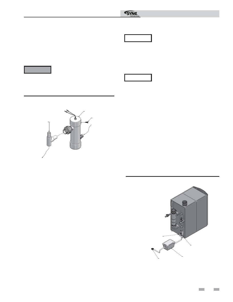
Condensate disposal
1.
This boiler is a high efficiency appliance that produces
condensate.
2.
The rear of the boiler has a 1/2 inch (12.7 mm) PVC
union for connection of a 1/2 inch (12.7 mm) PVC pipe
(FIG. 2-2).
3.
Slope condensate tubing down and away from the
boiler into a drain or condensate neutralizing filter.
Condensate from the SYNC will be slightly acidic
(typically with a pH from 3 to 5). Install a neutralizing
filter if required by local codes.
A Neutralizer Kit (FIG. 2-2) is available from the factory
(KIT3046).
4.
Install the 1/2 inch (12.7 mm) PVC tee assembly
(shipped with the unit) as shown in FIG. 2-2.
5.
Leave the top of the 1/2 inch (12.7 mm) tee OPEN. This
is needed as a vacuum break.
6.
Do not expose condensate line to freezing temperatures.
Use materials approved by the authority
having jurisdiction. In the absence of
other authority, PVC and CPVC pipe must
comply with ASTM D1785 or D2845.
Cement and primer must comply with
ASME D2564 or F493. For Canada use
CSA or ULC certified PVC or CPVC pipe,
fittings, and cement.
7.
A condensate removal pump is required if the boiler is
below the drain. When installing a condensate pump,
select one approved for use with condensing boilers and
furnaces. The pump should have an overflow switch to
prevent property damage from condensate spillage. Call
your qualified service technician to inspect
the boiler and system.
NOTICE
NOTICE
To allow for proper drainage on large
horizontal runs, a second line vent may be
required and tubing size may need to
increase to 1 inch.
The condensate line must remain
unobstructed, allowing free flow of
condensate. If condensate is allowed to
freeze in the line or if the line is obstructed
in any other manner, condensate can exit
from the boiler tee, resulting in potential
water damage to property. Call your
qualified service technician to inspect
the boiler and system.
Figure 2-2 Condensate Disposal
NEUTRALIZER KIT
1/2" (12.7 mm) PVC UNION
(FACTORY SUPPLIED)
1/2" (12.7 mm) PVC TEE ASSEMBLY
(FACTORY SUPPLIED)
FLOOR DRAIN
OR DRAIN PAN