Troubleshooting and repair, Continued) – Lincoln Electric SVM143-A User Manual
Page 64
F-20
TROUBLESHOOTING AND REPAIR
F-20
DH-10
the control board or associated leads or
plugs may be faulty. See the Wiring
Diagram.
6. Activate the gun trigger. Make sure the
motor is running. Check for the pres-
ence of approximately 5.0 VDC from
blue lead #555 (+) to black lead #500
(-). The 5.0 VDC represents the correct
feedback voltage from the hall effect
device to the control board.
7. If the above voltage reading is not cor-
rect, the hall effect device may need to
be adjusted or replaced. See
TEST PROCEDURE
1. Remove input power to the DH-10 unit.
2. Using the 5/16 in. nutdriver, remove the
wire drive cover.
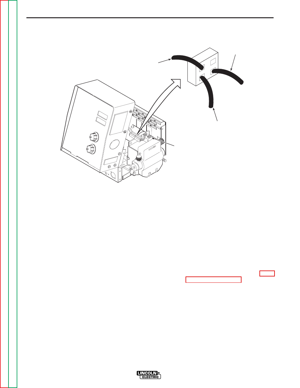
3. Locate the three hall effect leads (blue,
red and black). See Figure F.2.
4. Apply the correct input power (42 VAC)
to the DH-10.
5. Check for approximately 12 VDC from
red lead #512 (+) to black lead #500 (-).
If the 12 VDC is NOT present or low,
FIGURE F.2 — TACH FEEDBACK TEST.
LINCOLN
ELECTRIC
LINCOLN
ELECTRIC
HALL EFFECT
DEVICE (TACH)
#500
BLACK
#512
RED
#555
BLUE
TACH ADJUSTMENT AND FEEDBACK TEST
(continued)