2 nonvolatile memory, 3 dip switches, 4 control outputs – Liebert CHALLENGER 3000 User Manual
Page 36: Table 12 control output leds, Table 12, Control output leds
Operation with Advanced Microprocessor with Graphics Control
28
3.13.2 Nonvolatile Memory
All critical information is stored in nonvolatile memory. Setpoints, setup parameters, and component
run hours are kept inside the microcontroller in EEPROM. Information retained for data logging,
24 hour component run hour graphs, alarm history, and the water detection floor plan is kept in non-
volatile RAM.
3.13.3 DIP Switches
Equipment options are selected and enabled using DIP switches 1 to 7. These are located at the upper
left of the control board and are labeled SW1. Switch 1 is at the top. These switches are factory set
and should not require any user changes. The setting and function of the switches can be read from
the LCD (see 3.8.4 - DIP Switches).
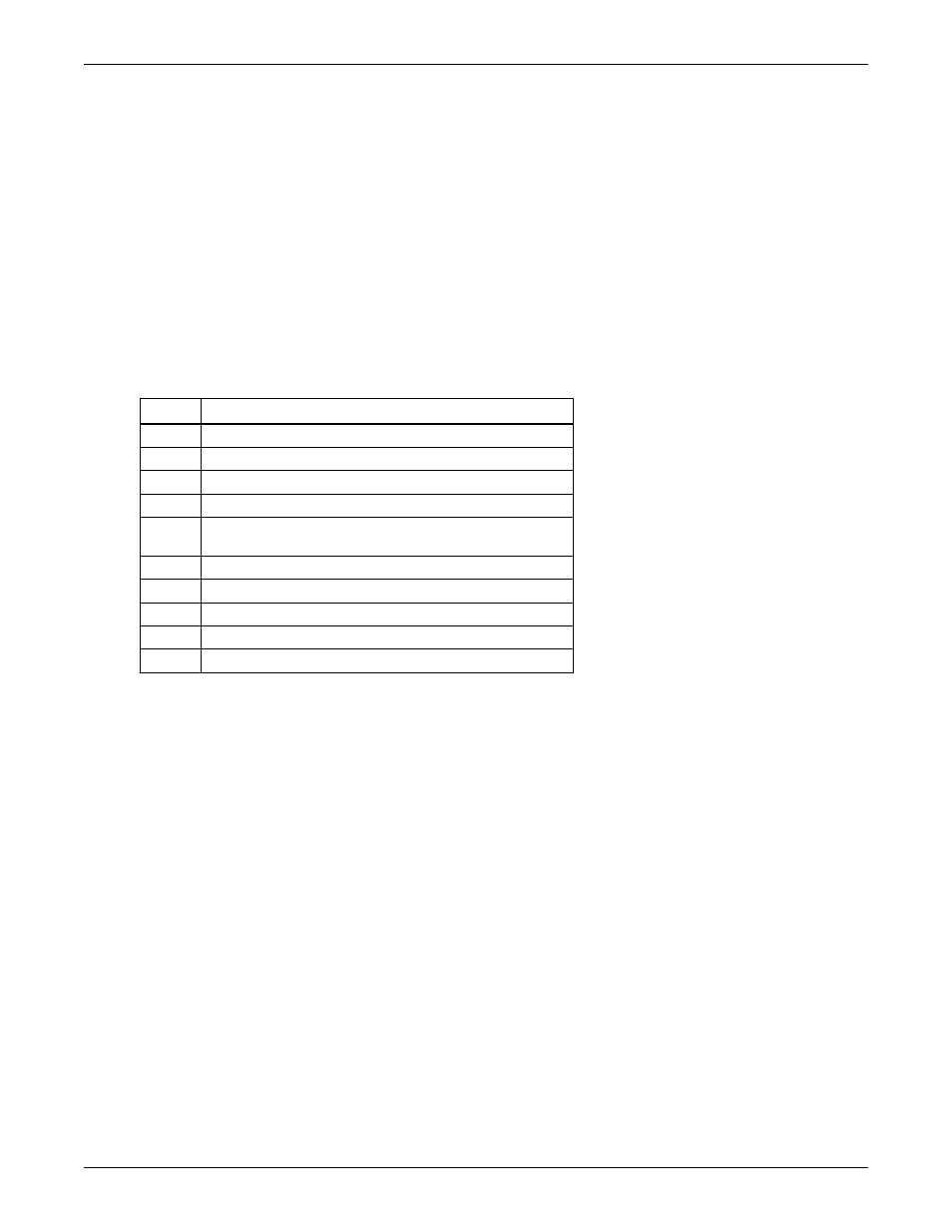
3.13.4 Control Outputs
Active control outputs are indicated with LEDs on the lower section of the control board. Each LED is
lit if the control output is active (on). Use these LEDs to assist in troubleshooting the system.
Table 12
Control output LEDs
LED
Control Output
R5
Heat Rejection
LLSV
Liquid Line Solenoid Valve
HGBP
Hot Gas By-Pass
C1
Compressor
RH1
Reheat Stage 1 or Hot Gas, Hot Water Reheat Solenoid
or SCR Reheats
RH2
Reheat Stage 2
HUM
Humidifier
FAN
Main Fan
HMV
Humidifier Make-Up Valve
LLSV2
Part Coil Solenoid Valve