Land Pride Rotary Cutters RCR1884 User Manual
Page 28
26
Section 5: Maintenance and Lubrication
RCR1884 Series Rotary Cutter 312-880M
2/03/12
7.
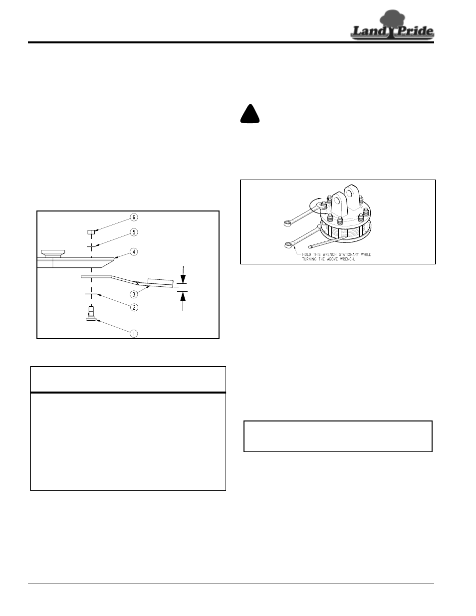
Start by assembling blades without shim (#2). Insert
blade bolt (#1) through blade (#3), dish pan (#4) and
flat washer (#5). Temporary secure blade with a used
1 1/8"-12 nut. Draw nut up snug. Do not tighten.
8.
Check blade deflection. If deflection is greater than
3/4", remove blade bolt and reassemble as before
except include shim (#2) in the assembly. Select
shim thickness based on deflection. The greater the
deflection, the thicker the shim.
9.
Once blade deflection is correct, replace used nut
with new locknut (#6) and torque to 450 ft-lbs.
10. Replace blade bolt access cover.
11. If replacing dishpan (#4), nut on gearbox output shaft
should be torqued to 450 ft-lbs. minimum and cotter
pin installed in nut with legs securely bent around
nut.
Cutter Blade Assembly
Figure 5-2
Slip-Clutch Protected Drivelines
Cutter drive components are protected from shock loads
by a friction slip-clutch. The clutch must be capable of
slippage during operation to protect the gearbox,
driveline and other drive train parts.
Clutch Run-In
Friction clutches should be “run-in” prior to initial
operation and after long periods of inactivity to remove
3/4" maximum
blade deflection
when blade
bolts are tight
24590
Land Pride Cutter Blade Parts
Item Part No.
Part Description
318-586A
BLADE BOLT KIT
(Includes items 1, 2, 5, & 6 below)
1
802-277C
BLADE BOLT 1 1/8-12 x 3 7/16 WITH KEY
2
312-075D
BLADE SPACER 16 GA. (.060")
2
312-082D
BLADE SPACER 18 GA. (.048")
2
312-089D
BLADE SPACER 20 GA. (.036")
2
312-808D
BLADE SPACER 24 GA. (.024")
3
820-138C
CUTTER BLADE 1/2 x 4 x 31 CCW
4
312-881H
27 x 10G OVAL DISHPAN WELDMENT
5
804-147C
WASHER FLAT 1 HARD ASTMF436
6
803-170C
NUT HEX TOP LOCK 1 1/8-12 PLATE
any oxidation that may have accumulated on friction
surfaces. To prevent driveline and gear box damage,
repeat “run-in” instructions at beginning of each season
and when moisture and/or condensation seizes inner
friction plates.
!
WARNING
Engage parking brake, disengage PTO, shut off tractor, and
remove key before dismounting tractor to make adjustments.
Refer to Figure 5-3:
1.
Using a pencil or other marker, scribe a line across the
exposed edges of the clutch plates and friction discs.
Clutch
Figure 5-3
2.
Carefully loosen each of the 8 spring retainer nuts on
the clutch housing a total of EXACTLY 2 revolutions.
It will be necessary to hold the hex end of the retainer
bolt in order to count the exact number of revolutions.
3.
Start tractor and engage driveline for 2-3 seconds to
permit slippage of the clutch surfaces. Disengage
the PTO, then re-engage a second time for 2-3
seconds. Disengage the PTO, shut off tractor and
remove key. Wait for all components to stop before
dismounting from tractor.
4.
Inspect clutch and ensure that scribed markings
made on the clutch plates have changed position.
Slippage has not occurred if any two marks on the
friction disc and plate are still aligned.
5.
Tighten each spring retainer nut on the clutch
housing exactly 2 revolutions to restore clutch to
original setting pressure. See “Clutch Assembly”
on page 27 for exact spring length.
6.
The clutch should be checked during the first hour of
cutting and periodically each week. An additional set
of scribe marks can be added to check for slippage.
Clutch Disassembly
Refer to Figure 5-4 on page 27:
Disassembly of the clutch is simply a matter of removing
the spring retainer nuts (#1), springs (#2) and bolts (#3)
from the assembly. Each friction disc (#4) must then be
separated from the metal surface adjacent to it.
13693
IMPORTANT: The clutch must be disassembled to
separate friction disc plates if one or more friction
disc did not slip during clutch run-in operation.