Ln-25 pro wire feeder, Electrical diagrams, G-10 – Lincoln Electric LN-25 SVM179-B User Manual
Page 88: Ln-25™ pro
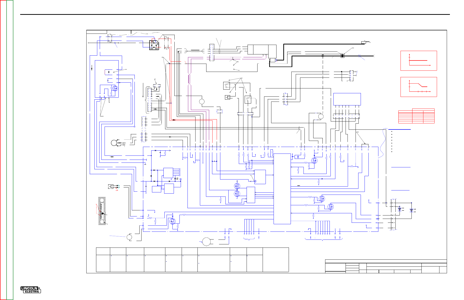
ElECTriCal DiaGrams
G-10
lN-25™ prO
sChEmaTiC - lN-25 prO - COmplETE maChiNE CODEs 11620, 11621, 11716, 11717 - (G5683-2) pG1
G5683-2
LN-25 PRO ANALOG
MACHINE SCHEMATIC
NONE
G5683-1
DO NOT SCALE THIS DRAWING
EQUIPMENT TYPE:
SUBJECT:
SCALE:
UF
CRM40943
1
PAGE ___ OF ___
2
ENGINEERING CONTROLLED
MANUFACTURER:
No
THIS DOCUMENT CONTAINS PROPRIETARY INFORMATION OWNED BY LINCOLN GLOBAL, INC. AND MAY NOT BE DUPLICATED, COMMUNICATED
TO OTHER PARTIES OR USED FOR ANY PURPOSE WITHOUT THE EXPRESS WRITTEN PERMISSION OF LINCOLN GLOBAL, INC.
PROPRIETARY & CONFIDENTIAL:
t
MATERIAL TOLERANCE (" ") TO AGREE
WITH PUBLISHED STANDARDS.
ON ALL ANGLES IS ± .5 OF A DEGREE
ON 3 PLACE DECIMALS IS ± .002 in. (± 0.05 mm)
ON 2 PLACE DECIMALS IS ± .02 in. (± 0.5 mm)
UNLESS OTHERWISE SPECIFIED TOLERANCE:
MANUFACTURING TOLERANCE PER E2056
RELEASED A.03 FROM "X".
CHANGE DETAIL:
REFERENCE:
MATERIAL
DISPOSITION:
APPROVAL
DATE:
PROJECT
NUMBER:
DOCUMENT
NUMBER:
DOCUMENT
REVISION:
IF PRINTED
@ A1 SIZE
UNITS:
INCH
11/6/2009
tpearn
ENYEDY
BS
DRAWN BY:
ENGINEER:
CLEVELAND
APPROVED:
CONTROL:
A
G56
83
-2
LN-25 PRO WIRE FEEDER
Start-Up
On power-up, the LN-25 PRO will light the motor thermal LED and
polarity LED 2-3 seconds.
If the feeder is powered-up with the trigger depressed, welding will
not start until the trigger is released and then depressed again.
Notes:
Motor overcurrent limit varies with WFS.
FEED
PLATE
67C & 67D
J4-10
1
4
3
2
6
5
P9
8
7
MOTOR /
GEARBOX
W
B
551
550
531
L4
537
534
72 HZ TO 1.2 KHZ
R-B 15.0 VDC
B-U 6.2 VDC ANY SPEED
(METER DEPENDENT)
Motor is located
behind
glastic panel
Gearbox ratio is 23.5:1
Motor case is at
electrode potential
From Power Source
(Electrode Connection)
J4-7
0-5V PULSE SIGNAL
FREQUENCY = SPEED
WIRE FEED
SPEED
0V = MIN SPEED
5V = MAX SPEED
GAS PURGE
FLEXIBLE POWER P.C. BOARD
SCHEMATIC = G4783
Top of motor
Motor resistance
is 1.5 ohms
Leads Pass through
toroid 2 times.
R
U
B
Located on
Case front
Leads Pass
through
toroid 2 times.
ISOLATED 2-4 TO
POWER SOURCE
BLACK
RED
FAN
+
-
S4
GAS PURGE
PUSHBUTTON
SWITCH (N.O.)
612
610
13.5 VDC WHEN
NOT DEPRESSED
J6-1
J6-7
J2-1
(LOCATED INSIDEOF
CONTROL BOX)
FAN BLOWS AIR ACROSS
CONTROL PC BOARD
CONTINOUSLY AT 6200 RPMS.
GAS
SOLENOID
690
691
J4-4
J4-3
J2-5
100K
ohm
+15V
J3-7
+5V
J3
-1
J3
-2
J3
-3
J3
-4
J3
-5
PROGRAMMING PCB
FACTORY USE ONLY
GAS SOLENOID
-
+
WORK
CLIP
+35V
POWER
SUPPLY
POWER
SUPPLY
+5V SPI
+15V SPI
OVER
VOLTAGE
PROTECTION
ISO
LED
35VDC
+5VDC
+15V ISO
-15V
COM
MOTOR
SUPPLY
COM
J5-1
J5-8
621A
Located on Case Front
J4-11 J4-12 J4-6
100K
ohm
+5V
J3-6
J3-8
+5V SPI
J4-9
10K
ohm
+15V
COM
534
537
531
J4-1
J4-2
550
551
TACH
FEEDBACK
Model
Ranger 8,9
Classic
Ranger 250, 305
Commander 300,400,500
(Common Analog
Controls)
V350
(Common Digital
Controls)
DC-400, 600
Square Wave TIG 300/355
Miller Inverters
STT II
K2613-1
K2613-2
Recommended
all CV
operation.
Recommended for
CV operation.
(Wire Feed
Module Required)
Recommended for CV
operation.
Recommended
for CV
operation.
May be used for
pulse welding if
the welding
procedure is
qualified by the
customer.
Recommended
for CV and CC
operation.
Not recommended for CC operation
because the customer may
experience short contactor life from
inductive nature of the power source.
Not recommended with high frequency
TIG starti ng.
Recommended
for CV voltage
sense operation.
Not
recommended for
use when pulse
welding.
Not recommended
for STT operation.
Note:
Most semiautomatic wire
welding processes perform
better using constant voltage
power sources. Be sure the
proper power source is used
for your application. Contactor
life may be shortened in
applications using CC
machines with high OCV.
J5-6
J5-7
21D
67F
721
J5-5
ANALOG
VOLTMETER
667B
721
-
+
TRIGGER
-15
+15
721 IS DRIVEN NEGATIVE TO COMPENSATE
FOR THE METER FOR DIODE DROP ERROR
ON THE BRIDGE
METER
COMPENSATION
CIRCUIT
POLARITY
SENSE
PROGRAM
BURNBACK
MOTOR
DRIVE
CIRCUIT
MOTOR VOLTAGE
MOTOR CURRENT
BRAKE
DRIVE
BRAKE
DRIVE
PWM
0.05K
ohm
L5
J6-3
J6-2
587
530
J6-4
523
J6-6
509A
+15V
COLD FEED
CC/VV
TRIGGER INTERLOCK / 2 STEP
S1, S2 & S3 Located
on Wire Drive Panel
CC
509D
CV
509E
TRIGGER INTERLOCK
(NOT PRESENT ON K2613-3)
S1
587
2-STEP
Located on Wire
Drive Panel
Trigger Interlock does not stop
welding when the arc is broken.
Pull and release to end the weld.
509B
S2
523
S3
COLD FEED
530A
509E
(LOCATED AT REAR
OF FEEDER)
667C
0V=COLD FEED
(N.O.)
15V=CV
0V=CC
15V=2 STEP
0V=TRIGGER
INTERLOCK
4B
606A
2
4
+15V
J5-4 J5-3
MOV
MACHINE
OUTPUT
ENABLE
CONTACTOR DRIVE
COM
+35V
J4-8 J4-5
CONTACTOR
4 O COIL
0 VDC OPEN
3 VDC CLOSED
12 VDC COIL
PWM CONTROLLED
507
578
20
ohm
0V = OFF
20msec ---- 250msec
605
601
J2-6 J2-3
608
607
J2-7
COM
YELLOW THERMAL LED
COM
POLARITY LED
J6-11
1W
J6-14
B
+5V SPI
GREEN
POLARITY
LED
YELLOW
MOTOR
THERMAL
LED
ARC ESTABLISHED
J1-2 J1-1
+5V SPI +15V
J1-10
J1
-8
J1
-6
J1
-5
J1
-4
J1
-9
J1
-3
J1
-7
SC
LK
CS
3
CS
2
CS
1
CS
0
M
O
SI
M
IS
O
SPI DIGITAlL COMMUNICATION
J6-8
-15V
GAS
ON - OFF
GAS
FLOW
ENABLE
Located under
Wire Drive Panel
(LOCATED AT OUTSIDE
REAR OF FEEDER)
10K/2W
0 VDC MIN. WFS
5 VDC MAX. WFS
WIRE FEED SPEED
CONTROL
POTENTIOMETER
621
667
11
10
P7
12
Connector located
behind case front
COM
15
14
(LOCATED AT TOP
FRONT OF FEEDER)
MICRO
CONTROLLER
COM
MOTOR
SUPPLY
6
8
7
5
1
3
4
6
2
8
7
9
10
J18
1
P16
Located on
top of motor
PLASTIC HOUSED BOLTED
CONNECTION (BASE CENTER)
TIMER KIT P.C. BOARD
(OPTIONAL)
SCHEMATIC = M21341
SEE PAGE 2
L12081 2.6 V @ 50 IPM
27 V @ 700 IPM
L13084 2.6 V @ 25 IPM
32 V @ 400 IPM
0V.=TRIGGER
CLOSED
15VDC.=TRIGGER
OPEN
Located on
Case Front
TRIGGER
INPUT
TRIGGER CONNECTOR
J14
622A
500A
E
B
C
D
A
P7-1
67D
67C
667B
67B
4
1
3
6
67C
67B
IN HARNESS
CENTER BASE
AREA
P7 = 16 PIN
P17 = 6 PIN (Both are located on lower front)
577A
576A
575A
577A
575A
576A
577A
576A
575A
77C
76C
75C
531
537
534
40V MAX.
21B
.05 uF
600 V
707
608
607
J2-8
4B
gun connector
4 of 4
3 of 4
J6-9 J6-10
622
500
+15V
2 of 2
P17
P7
1 of 4
P7
When tach feed back is lost,
the voltage to the motor is a
constant 10VDC.
(controlled by software)
P17
case front
strain rel
ief
1 of 2
5
2 of 4
copper bar
copper bar
weld cable
13
2B
1B
R1
D1
case back
strain rel
ief
509C
21A
21C
21E
JUMPER TOGETHER FOR
EXTRA TORQUE MACHINE
P60
3
4
5
6
7
8
601
509B
605
2
1
3
4
2
J2-2
+5V
606
EXTRA TORQUE
TAKEN WITH 40 V INPUT
IN CV MODE.
667A
WFS limited by arc voltage when operating across the arc
Feeder Input Volts Standard Gear Extra Torque
15
280
210
17
340
235
21
440
400
24
520
400
27
600
400
Maximum WFS
EXTRA
TORQUE
Control Board Summary
Converts arc power to a usable control circuit voltage.
Receives switch signals from Trigger, Cold Feed, Gas Purge
Reads WFS potentiometer.
Communicates with optional timer kit.
Controls motor speed with PWM.
Turns Gas Solenoid on, off, PWM.
Reads the motor tachometer.
Operating Voltage= 15-110 VDC.
Shut down Voltage= 130 VDC.
Thermal light turns on when shutdown voltage exceeded.
Code and Serial numbers are below Wire Drive on plastic
housing Nameplate.
Thermal “Yellow” Light
Motor Over Current
Motor and trigger disabled for 30 seconds.
Must retrigger to start welding after 30 seconds pass.
Shutdown Voltage exceeded
May occur with some inverters.
May occur with some CC machines with high
inductance.
Polarity “Green” Light
On= Positive Polarity
Off= Negative Polarity
708
J6-5
9
2W
J6-12
16
509B
The WFS range of the LN-25 PRO
Normal Speed = 40- 700 IPM.
Extra Torque = 25- 400 IPM.
Before 2-20-2009
After 2-20-2009
*Extra Torque
370
530
700
180*
257*
400*
3.5
4.5
3.5
4.5
Preset
WFS
Current
Level
Current
Level
Preset
WFS
77C
76C
75C
610
612
B1
B2
C2
C1
C1
C2
B1
B2
667D
667E
B2
B1
621
667D
25 TO 35
NORMAL
FLOW
RATE
GOOD FOR Ar, CO2,
CO2/Ar BLENDS
(OUTSIDE
BACK OF
CASE)
FLOW METER
22 O COIL
0 VDC OPEN
4 VDC CLOSED
12 VDC COIL
PWM CONTROLLED
BALL FLOAT
USE MIDDLE
OF BALL TO
SET
ADJUST VALVE
NOT PRESENT
ON S27505
J61-1
J61-3
J61-4
J61-2
J62-2
J62-1
MOTOR FILTER P.C.
BOARD SCHEMATIC=
S27592 BEFORE 6/15/2009
S27505 AFTER 6/15/2009
USED TO DISCHARGE
POWER SUPPLY CAP
AFTER A HIGH VOLTAGE
TRANSIENT. LATER
RELOCATED TO THE
CONTROL BOARD.
USED FOR FILTERING
INVERTER NOISE
J15
14 PIN REMOTE
LEADS ARE
PRESENT BUT
NOT USED IN
THIS UNIT.
NOT
USED
J2-10
555
622
500
4
2
555
3
555A
622B
G-10
NOTE:
This diagram is for reference only. It may not be accurate for all machines covered by this manual.