Installation – Lincoln Electric LN-25 SVM179-B User Manual
Page 13
INSTALLATION
A-7
A-7
LN-25™ PRO
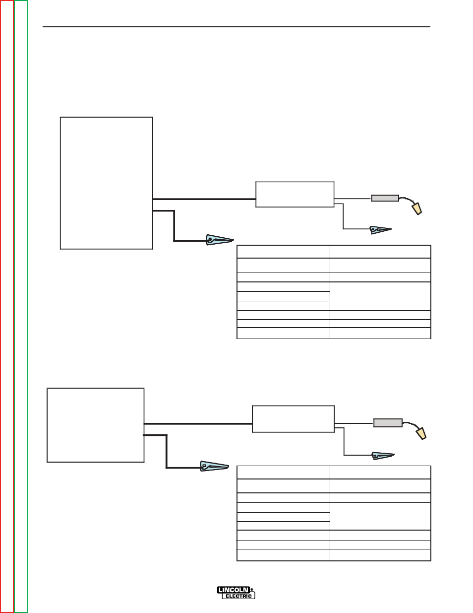
ACROSS THE ARC SET-UPS
CC Power Sources with Output Terminals Always
Hot (See Figure A.5)
If the power source has a Remote/Local switch, place
the switch in the Local position.
Place the Power Source CC/CV switch (if present) or
Range Switch in the CV position if possible.
Set the CV/CC switch in the feeder to match the power
source.
CV
Power Sources with Stud Connectors and
Remote/Local Switch (See Figure A.6)
Place the power source Remote/Local switch in the
Local position.
Place CV/CC switch in the feeder in the "CV" position.
LN-25 PRO
(Across the Arc)
CC Power Source
Ranger 250, 250 LPG
Ranger 305G, 305D
Commander 300
Vantage 300, 400, 500
Air Vantage 500
Ranger 10,000
Ranger 3 phase
SAE 400 with CV adapter
Engine Driven welder with
Wire Feed Module
Work
Electrode
Work clip
LN-25 PRO
(Across the Arc)
Work
Electrode
Work clip
CV-655
CV-400
DC-400
DC-600
DC-655
V450-Pro
FIGURE A.5
FIGURE A.6
K#
K2613-1
K2613-2
KP1695-XX
KP1696-XX
KP1697-XX
See Magnum Literature
K1803-1
Description
LN-25™ PRO Wire Feeder
LN-25™ PRO Extra Torque
Drive Roll Kit
Welding Gun
CC power Source
Welding Cables
POWER SOURCE TO LN-25™ PRO
CABLE CONNECTION DIAGRAMS
K#
K2613-1
K2613-2
KP1695-XX
KP1696-XX
KP1697-XX
See magnum Literature
K1803-1
Description
LN-25™ PRO Wire Feeder
LN-25™ PRO Extra Torque
Drive Roll Kit
Welding Gun
CV power Source
Welding Cables