Krell Industries DVD Player User Manual
Page 68
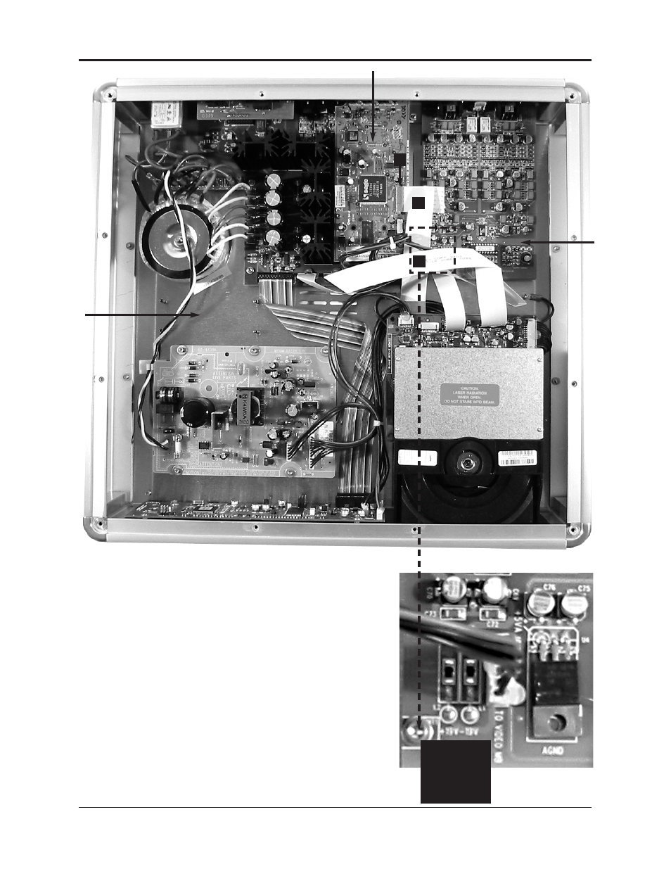
Figure 2
Showcase DVD Interior,
Before HDMI Upgrade
Installation
3
22-pin, 7-inch flat digital video
cable
4
Locking socket
5
4-40 x 7/16-inch hex screw.
The pin standoff is below this
screw.
Figure 2 Inset
Analog Output PCB,
Left Front Corner
5
4-40 x 7/16-inch hex screw.
The pin standoff is below this
screw.
Showcase DVD / 3
HDMI Upgrade
4
3
5
5 Lift the cables
to expose the
through hole at
MT1 on the ana-
log output PCB.
Progressive output PCB
Analog
output
PCB
Position the
HDMI power
PCB here. (See
pages
4-5.)