Connecting wires to terminals (kdc-3029r) – Kenwood KDC-MP4029G User Manual
Page 31
English
|
31
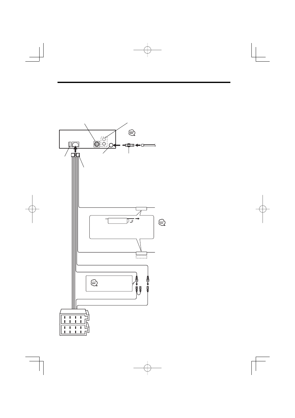
Connecting Wires to Terminals (KDC-3029R)
P.CONT
ANT.CONT
1
2
3
4
5
6
7
8
1
2
3
4
5
6
7
8
MUTE
Battery wire (Yellow)
Ignition wire (Red)
FM/AM antenna
input
Antenna Cord (ISO)
Antenna Conversion Adaptor
(ISO–JASO) (Accessory
6)
To connect the KENWOOD
navigation system, consult
your navigation manual.
Wiring harness
(Accessory
1)
If no connections are made, do
not let the wire come out from
the tab.
Power control/ Motor
antenna control wire
(Blue/White)
TEL mute wire (Brown)
Connect either to the power
control terminal when using the
optional power amplifier, or to
the antenna control terminal in
the vehicle.
Connect to the terminal that
is grounded when either the
telephone rings or during
conversation.
A –7 Pin (Red)
A–4 Pin (Yellow)
Connector A
Connector B
Fuse (10A)
See next page
To connect these leads, refer to the relevant instruction manuals.
Rear left output (White)/
Rear right output (Red)
To KENWOOD disc changer/
External optional accessory